Rj45 connectors, Port indicators – Allied Telesis AT-TS24TR User Manual
Page 63
AT-TS12TR Connectivity
48
RJ45 Connectors
The AT-TS12TR uses 12 RJ45 connectors, thus eliminating the need for a
Telco-type cabling adapter. Figure 45 shows a sample RJ45 connector.
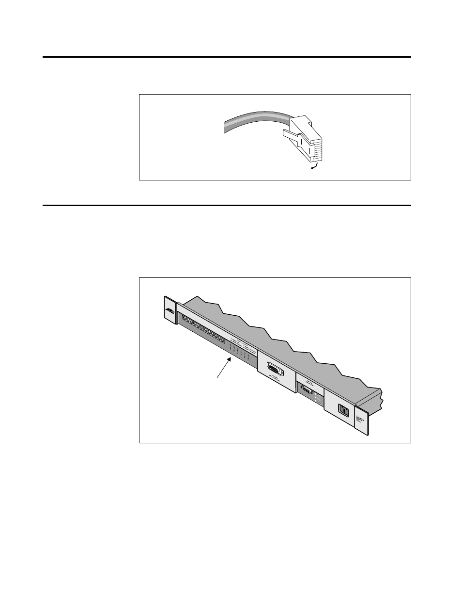
Port Indicators
The port indicators on the AT-TurboStack hub front panels provide visual
diagnostic and activity information for network analysis. The AT-TS12TR
provides a central bank of indicators for box-level monitoring.
As shown in Figure 46, each 10BASE-T port supports the following
indicator functions with one single-color front panel LED per port:
GREEN LINK (Steady Green)—This indicates that the particular port
has a valid link and is not partitioned.
GREEN RECEIVE (Flashing Green)—When a port’s LED is blinking,
the port is receiving Ethernet packets.
NO LINK (No Light)—If the Link Test function is not met by the
10BASE-T device at the opposite end of the UTP segment, this LED will
not illuminate. This may occur if the workstation at the end of the
segment is turned OFF or if the UTP segment is disrupted or damaged.
Figure 45: RJ45 Connector
Pin 1
Figure 46: AT-TS12TR Port
LEDs
Port activity LEDs