Terminator switch – Allied Telesis AT-TS24TR User Manual
Page 52
AT-TS08 Connectivity
36
Terminator Switch
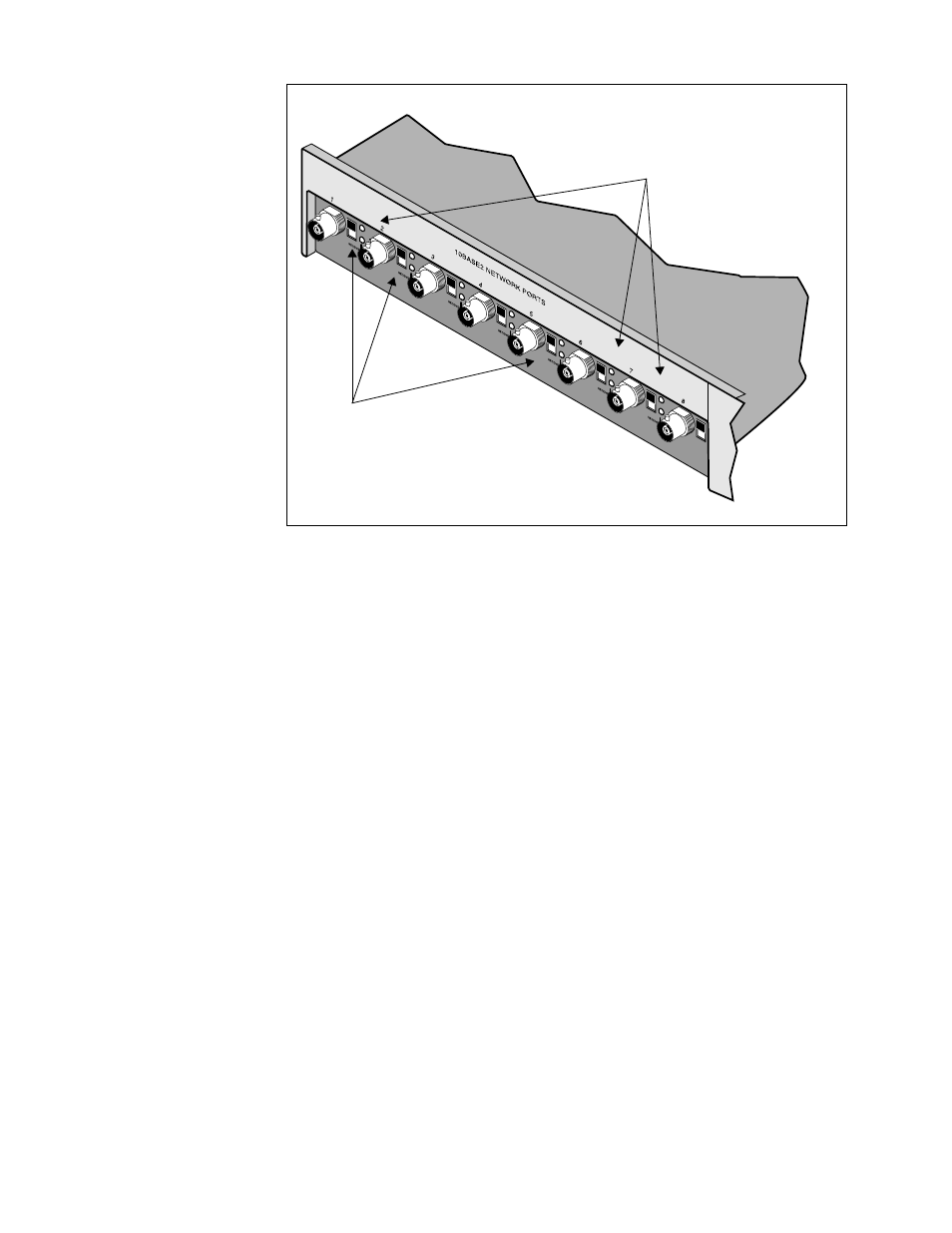
Figure 33 shows the location of the 50
Ω
Terminator switch included with
each BNC port receptacle:
0 = Terminator disabled—Use the OFF position if you are installing a
coaxial cable segment with a BNC-T connector on this port (see
Figure 31).
1 = Terminator enabled—Use the ON position if you are installing a
coaxial cable segment without a BNC-T connector at this port and the unit
is at the end of the cable (see Figure 31). This is the default switch
position.
Figure 33: AT-TS08 Port
Indicators
Port
LEDs
Terminator
switches
1 = terminator ON
0 = terminator OFF
This manual is related to the following products: