To remove a 10base2, 10base-t or fiber optic (10ba, Snap off the plastic cover plate on the install, Remove the two m3x6 flat-head appliqué screws – Allied Telesis AT-TS24TR User Manual
Page 40: Remove the 4-40 pan-head screws from the aui co, Store the removed 10base2, 10base-t, or 10base, To install an aui appliqué, Using the supplied screws, lock washers, and nu, Using the two m3x6 flat-head appliqué screws, a, Snap the at-tsa5 (aui) plastic cover plate in p, Back-panel features
TurboStack Hubs with Management
23
To remove a 10BASE2, 10BASE-T or fiber Optic (10BASE-FL)
appliqué
1.
Snap off the plastic cover plate on the installed 10BASE2, 10BASE-T,
or 10BASE-FL appliqué. (See Figure 11 on page 17.)
2.
Remove the two M3x6 flat-head appliqué screws (shown in Figure 19)
and pull out the appliqué.
3.
Remove the 4-40 pan-head screws from the AUI connector and ribbon
cable assembly (reverse of Step 3 and related Figure 18 above).
4.
Store the removed 10BASE2, 10BASE-T, or 10BASE-FL appliqué
assembly in a secure container for future use.
To install an AUI appliqué
1.
Using the supplied screws, lock washers, and nuts, attach the AUI
appliqué connector plate and locking bracket (slide-kit) to the AUI
connector. (See Figure 14 on page 20.)
2.
Using the two M3x6 flat-head appliqué screws, attach the AUI
appliqué to the hub faceplate. (See Figure 13 on page 20.)
3.
Snap the AT-TSA5 (AUI) plastic cover plate in place on the hub
faceplate. (See Figure 11 on page 17.)
Back-panel
Features
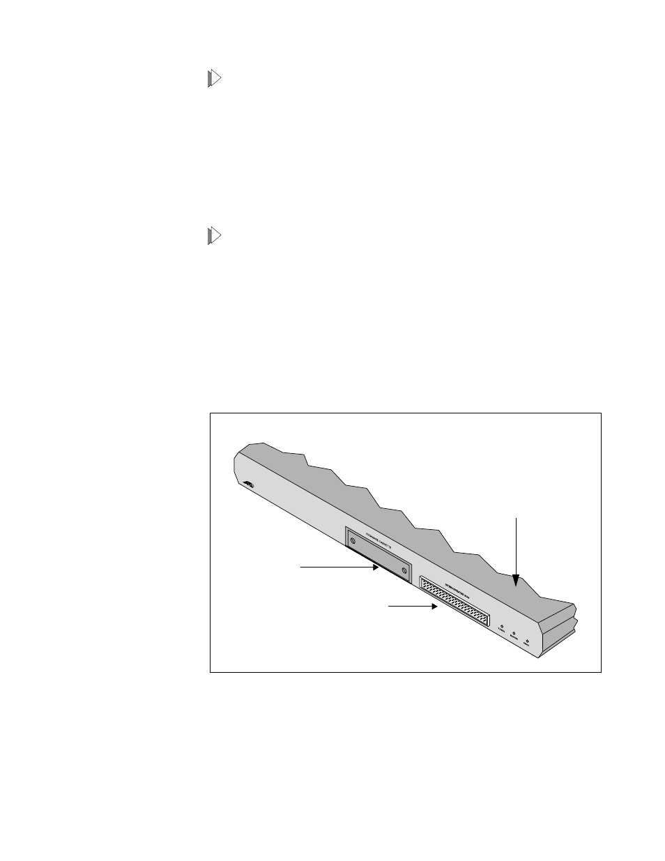
All TurboStack hubs with management capability have the same back
panel layout and features, shown in Figure 20.
❑
Firmware cassette port used to install new network management
software. (For more information, refer toTurboStack™ AT-S10
Firmware Module for TurboStack Hubs Operations Manual)
❑
Interrepeater bus connector that attaches the TurboStack module
to the backplane bus in a concentrator chassis
❑
Status indicators providing information on the hub as a whole. For
convenience, these LEDs appear on both the front and back panels.
Figure 20: TurboStack Hub
Back Panel
Firmware
cassette port
bus port
Interrepeater
Hub status LEDs