Appendix c rs232c/ttl level serial interface, Appendix d pulse output mode – Vaisala PTB220 User Manual
Page 87
A
PPENDIX
C __________________________________________ RS232C/TTL
LEVEL SERIAL INTERFACE
V
AISALA
_________________________________________________________________________ 81
APPENDIX C RS232C/TTL LEVEL SERIAL INTERFACE
The Appendix C shows connection of handshaking lines and the wave
forms, voltage levels and phases of the RS232C/TTL level serial
interface signals.
Handshaking lines (DCD, CTR, DSR, RTS and CTS) may have to be
connected at the host system end as illustrated below:
1 DCD
2
3
4 DTR
5
6 DSR
7 RTS
8 CTS
9
1
2
3
4 RTS
5 CTS
6 DSR
7
8 DCD
9
...
20 DTR
...
25
9-pin D connector
25-pin D connecto
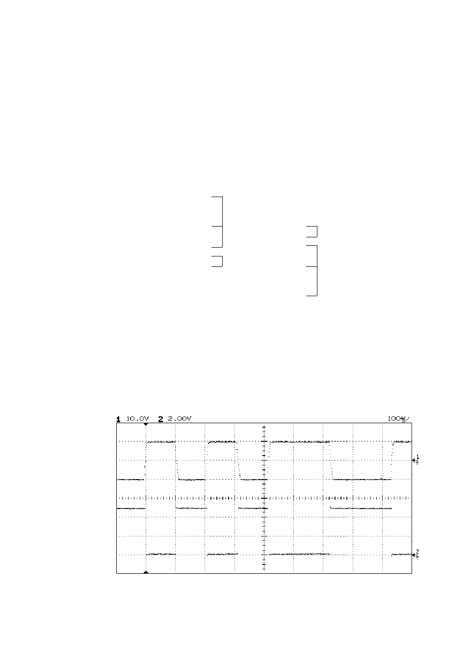
The next picture (below) shows a typical RS232C RX input signal
(upper signal) and TTL level serial RXD input signal (lower signal) at
baud rate 9600. The vertical scale is 10V/div for upper signal and
2V/div for lower signal. The ground level for each signal is shown
with a small arrow at the right. At the left, the signals are at rest. The
RXD inverted input signal has opposite phase compared to the RXD
signal shown here.