Block diagram – Vaisala PTB220 User Manual
Page 13
C
HAPTER
2___________________________________________________ PRODUCT DESCRIPTION
V
AISALA
__________________________________________________________________________ 7
Block diagram
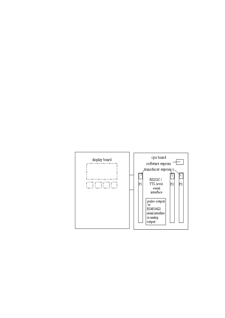
The PTB220 series digital barometers consist of a CPU board and 1, 2
or 3 pressure transducers (P1, P2 and P3). The number of pressure
transducers is order specific and the configuration cannot be changed
by the user. Usually the pressure transducers are connected to the
same pressure port. However, in case of two pressure transducers, the
barometer can have also two pressure ports, one for each transducer.
The various hardware configurations are illustrated on page 77.
The PTB220 series barometers always have a RS 232C full duplex
and a bidirectional TTL level serial interface. In addition, the
barometers have either a pulse output interface or an RS 485/422 two-
wire half duplex serial interface. The RS 485/422 interface is a
separate optional module inside the barometer. This interface module
is order specified and installed at the factory only. There is also an
optional factory set analog output module available. A LCD display
with backlight is also a possible configuration option.
The block diagram of the PTB220 series barometers is shown in
F
IGURE
2-3
F
IGURE
2-3
Block diagram of the PTB220 barometers