Appendix b pin assignments, Appendix c rs232c/ttl level serial interface – Vaisala PTB220 User Manual
Page 85
A
PPENDIX
B ___________________________________________________________
PIN ASSIGNMENTS
V
AISALA
_________________________________________________________________________ 79
APPENDIX B PIN ASSIGNMENTS
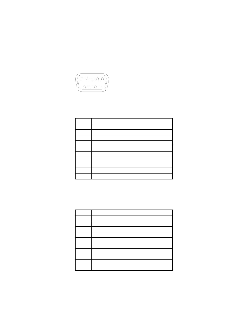
The pin assignment of the 9-pin female subD-connector of the
PTB220 series digital barometers seen from the front:
1
2
3
4
5
6
7
8
9
In barometers with RS232C/TTL level serial/pulse output interface,
the pin assignment is as follows:
PIN
SIGNAL
1
TX with diode
2
TX/TXD/TXD inverted
3
RX/RXD/RXD inverted
4
external power on/off control
5
ground for the RS 232C
6
pulse output (TTL level)
7
ground for supply voltage and TTL
level serial interface and pulse output
8
pulse trigger
9
supply voltage (10...30 VDC)
In case a common ground is needed for both the power supply and the
serial interface, the pin 7 should be used as the common ground.
In barometers with RS 232C/485/422 serial interface the pin
assignment is as follows:
PIN
SIGNAL
1
TX with diode
2
TX/TXD/TXD inverted
3
RX/RXD/RXD inverted
4
external power on/off control
5
ground for the RS 232C
6
RS 485/422 LO
7
ground for supply voltage and TTL
level serial interface
8
RS 485/422 HI
9
supply voltage (10...30 VDC)