Pdms, 25 dual pdu assembly – HP 3000 Enterprise Virtual Array User Manual
Page 77
1
0130a
2
3
5
4
5
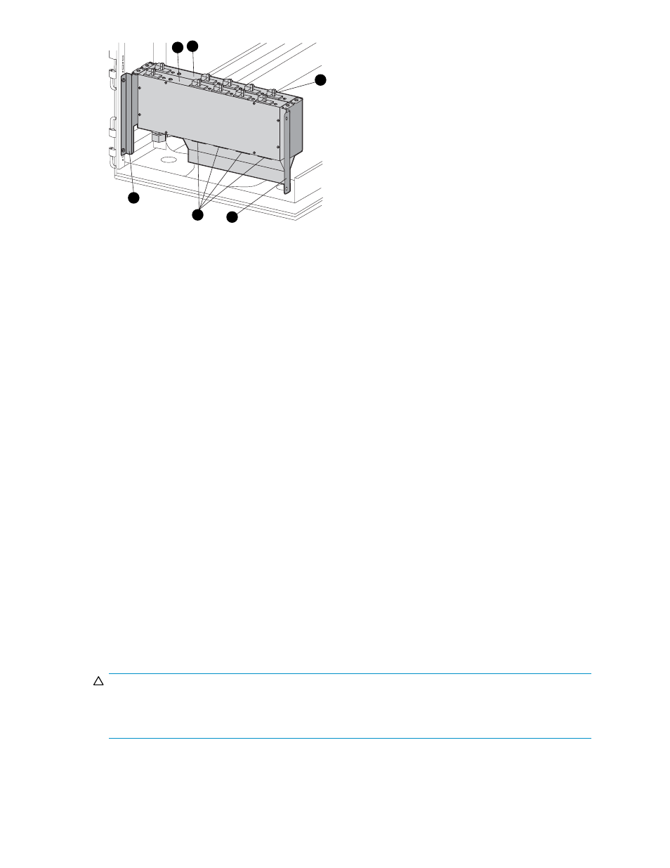
Figure 25 Dual PDU assembly
1. PDU 1
2. PDU 2
3. Circuit breakers
4. AC receptacles
5. Mounting hardware
PDU 1
PDU 1 connects to AC power distribution source 1. A PDU 1 failure:
•
Disables the power distribution circuit.
•
Removes power from PDMs 1, 2, and 3.
•
Disables PS 1 in the drive enclosures.
•
Disables the upper controller power supply.
PDU 2
PDU 2 connects to AC power distribution source 2. A PDU 2 failure:
•
Disables the power distribution circuit.
•
Removes power from PDMs 4, 5, and 6.
•
Disables PS 2 in the drive enclosures.
•
Disables the lower controller power supply.
PDMs
There are six PDMs mounted in the rear of each rack:
•
Three mounted on the left vertical rail connect to PDU 1.
•
Three mounted on the right vertical rail connected to PDU 2.
Each PDM has eight AC receptacles and one thermal circuit breaker. The PDMs distribute the AC power
from the PDUs to the enclosures. Two power sources exist for each controller pair and drive enclosure. If
a PDU fails, the system will remain operational.
CAUTION:
The AC power distribution within a rack ensures a balanced load to each PDU and reduces the possibility
of an overload condition. Changing the cabling to or from a PDM could cause an overload condition.
HP supports only the AC power distributions defined in this user guide.
Enterprise Virtual Array 3000/5000 user guide
77