HP StorageWorks 1510i Modular Smart Array User Manual
Page 31
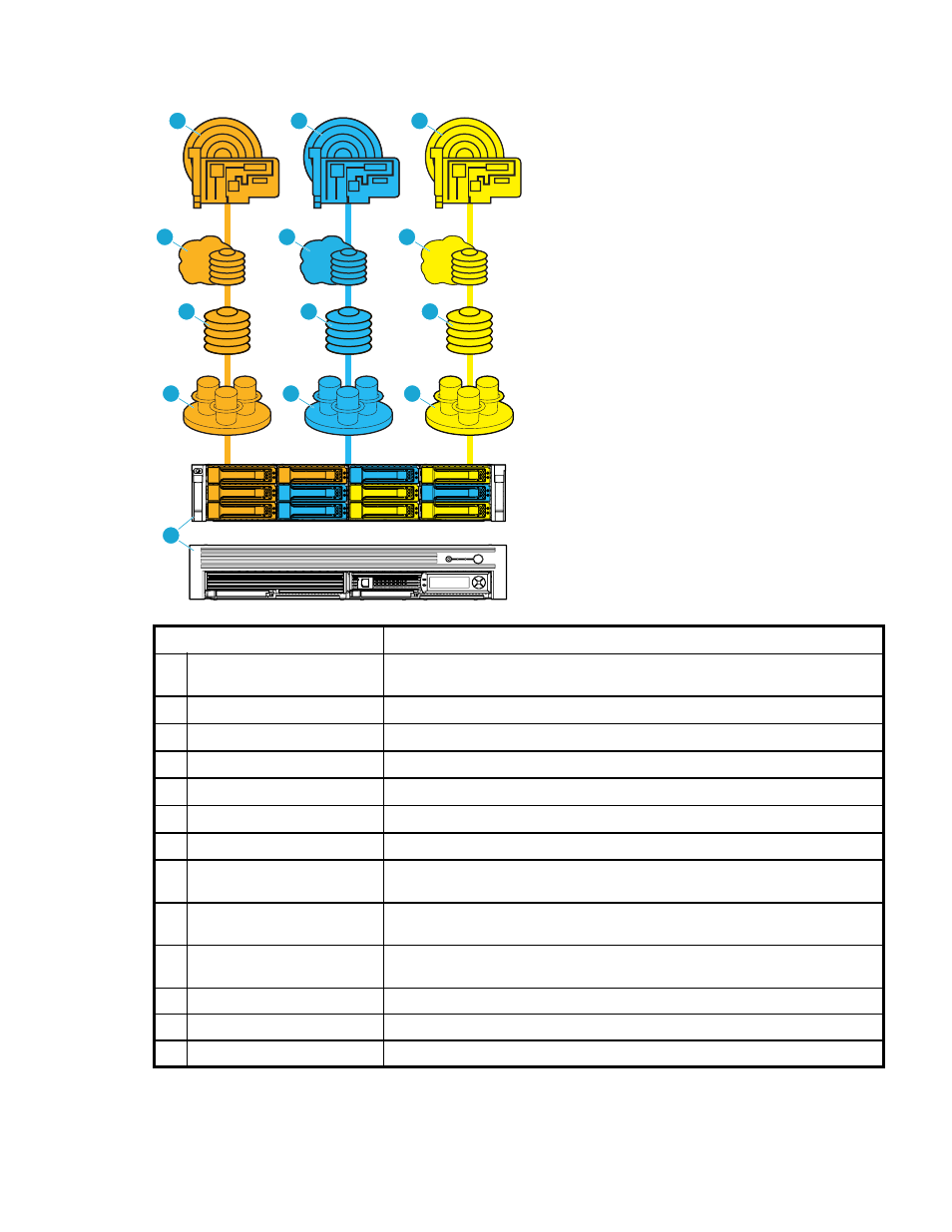
Sample configuration—Physical-to-logical storage diagram
15293
1
2
5
6
7
8
9
10
11
12
13
3
4
Item
Description
1
MSA1510i controller shelf and
MSA20 storage enclosure
Sample includes two array controllers and two 2-Port Ethernet iSCSI modules,
with twelve SATA hard drives in the storage enclosure.
2
Array A
Uses hard drives from bays 1, 2, 3, and 4.
3
Array B
Uses hard drives from bays 5, 6, and 7, with number 11 assigned as a spare.
4
Array C
Uses hard drives from bays 8, 9, and 10, with number 12 assigned as a spare.
5
Logical Drive 1
Uses all space from Array A, with RAID 1+0 fault tolerance.
6
Logical Drive 2
Uses all space from Array B, with RAID 5 fault tolerance.
7
Logical Drive 3
Uses all space from Array C, with RAID 5 fault tolerance.
8
Mapped Logical Drive 1
When Logical Drive 1 was mapped to this target (Target 1), it was renamed
to Mapped Logical Drive 1.
9
Mapped Logical Drive 1
When Logical Drive 2 was mapped to this target (Target 2), it was renamed
to Mapped Logical Drive 1.
10 Mapped Logical Drive 1
When Logical Drive 3 was mapped to this target (Target 3), it was renamed
to Mapped Logical Drive 1.
11
Target 1
12 Target 2
13 Target 3
HP Storage Management Utility user guide
31
- StorageWorks MSL6000 Tape Library (61 pages)
- Лент-е накопители HP StoreEver DAT (64 pages)
- Лент-е накопители HP StoreEver DAT (50 pages)
- StoreEver TapeAssure Software (40 pages)
- StoreEver Ultrium Tape Drives (75 pages)
- StoreEver Ultrium Tape Drives (60 pages)
- Linear Tape File System Software (28 pages)
- Linear Tape File System Software (25 pages)
- StoreEver Ultrium Tape Drives (78 pages)
- StoreEver Ultrium Tape Drives (76 pages)
- Linear Tape File System Software (20 pages)
- StoreEver Ultrium Tape Drives (61 pages)
- 2600fx Optical Disk Drive (65 pages)
- Ленточный автозагрузчик HP StorageWorks DAT 72x10 (58 pages)
- StorageWorks 1500cs Modular Smart Array (71 pages)
- 2000fc Modular Smart Array (150 pages)
- StorageWorks 1000 Modular Smart Array (72 pages)
- StorageWorks 1000 Modular Smart Array (81 pages)
- StorageWorks 1500cs Modular Smart Array (48 pages)
- StorageWorks 1500cs Modular Smart Array (52 pages)
- Servidor de almacenamiento HP ProLiant DL585 G2 (152 pages)
- Sistemas de almacenamiento de red HP StorageWorks X3000 (152 pages)
- Software de HP StoreVirtual VSA (127 pages)
- Software de HP StoreVirtual VSA (85 pages)
- X500 Data Vault (331 pages)
- StorageWorks 1000i Virtual Library System (122 pages)
- StorageWorks XP Remote Web Console Software (20 pages)
- 200 Storage Virtualization System (176 pages)
- XP Array Manager Software (101 pages)
- StorageWorks MSA 2.8 SAN Switch (307 pages)
- StorageWorks MSA 2.8 SAN Switch (22 pages)
- StorageWorks MSA 2.8 SAN Switch (104 pages)
- StorageWorks MSA 2.8 SAN Switch (270 pages)
- StorageWorks All-in-One SB600c Storage Blade (72 pages)
- StorageWorks All-in-One SB600c Storage Blade (80 pages)
- StorageWorks All-in-One SB600c Storage Blade (78 pages)
- StorageWorks All-in-One SB600c Storage Blade (60 pages)
- ProLiant DL585 G2 Storage-Server (150 pages)
- Data Protector Express Basic-Software (93 pages)
- Data Protector Express Basic-Software (83 pages)
- ProLiant DL185 G5 Storage Server (174 pages)
- ProLiant High Availability Storage Server (72 pages)
- P2000 G3 MSA Array Systems (58 pages)
- StorageWorks 2000fc G2 Modular Smart Array (76 pages)
- 2000I G2-Modular-Smart-Array (48 pages)