Technical data – KROHNE H250 M8-M9-M10 EN User Manual
Page 82
8
TECHNICAL DATA
82
H250
www.krohne.com
04/2011 - 4000269302 MA H250-R02 en
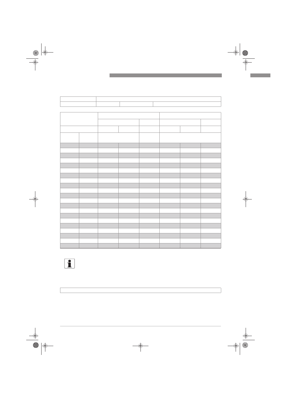
H250/C - Ceramic/PTFE
Reference condition for gas measurements:
Reference condition for gas measurements:
Reference condition for gas measurements:
Reference condition for gas measurements:
The flow measurement of gases are refered to
Nl/h or Nm
3
/h: Volume flow in Normal state 0°C, 1.013 bar abs. (DIN 1343)
Measuring span:
10 : 1
Declaration of flow:
Values = 100%
Water: 20°C [68°F]
Air: 20°C [68°F], 1.013 bar abs. [14.7 psia]
Flow rate
Max. pressure loss
Water
Air
Water
Air
Liner / Float
PTFE
Ceramic
Ceramic
PTFE
Ceramic
Ceramic
Nominal
size
Cone
[l/h]
[Nm
3
/h]
[mbar]
DN15, ½"
E 17.2
25
30
-
65
62
62
E 17.3
40
50
1.8
66
64
64
E 17.4
63
70
2.4
66
66
66
E 17.5
100
130
4
68
68
68
E 17.6
160
200
6.5
72
70
70
E 17.7
250
250
9
86
72
72
E 17.8
400
-
-
111
-
-
DN25, 1"
E 27.1
630
500
18
70
55
55
E 27.2
1000
700
22
80
60
60
E 27.3
1600
1100
30
108
70
70
E 27.4
2500
1600
50
158
82
82
E 27.5
4000
1
2500
75
290
100
100
DN50, 2"
E 57.1
4000
4500
140
81
70
70
E 57.2
6300
6300
200
110
80
80
E 57.3
10000
11000
350
170
110
110
E 57.4
16000
1
-
-
284
-
-
DN80, 3"
E 87.1
16000
16000
-
81
70
-
E 87.2
25000
25000
-
95
85
-
E 87.3
40000
1
-
-
243
-
-
DN100, 4"
E 107.1
40000
-
-
100
-
-
E 107.2
60000
1
-
-
225
-
-
1 special float
INFORMATION!
The oper. press. should be at least twice the pressure loss for liquids, and at least 5
times the pressure loss for gases! The specified pressure drops are valid for water and air at
maximum flow rate. Other flow ranges on request. Conversion of other media or operating data
(pressure, temperature, density, viscosity) is performed using the calculation method in
accordance with VDI /VDE Directive 3513
MA_H250_R02_en_269302_PRT.book Page 82 Tuesday, April 12, 2011 10:17 AM