Table 3-1. key functions (continued), Key functions -9, D 3-1 expla – KEPCO ATE-DMG SERIES User Manual
Page 43
ATE-DMG 042314
3-9
NOTE: Keys with dual functions are labeled with both a command and a number. The com-
mand label is referred to when the unit is in command entry status; the number is
referred to when the unit is in data entry status.
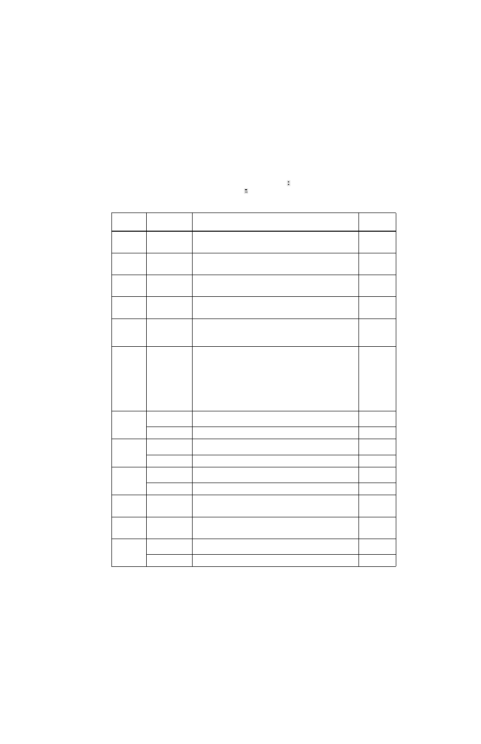
TABLE 3-1. KEY FUNCTIONS
KEY
POWER SUPPLY
STATUS ACTIVE
DESCRIPTION
REFERENCE
PARAGRAPH
OUTPUT
ON/OFF
Command Entry
If bottom line of LCD reads Output OFF, press to enable the output. If out-
put is on (voltage and current measurements displayed on bottom line of
LCD), press to disable the output.
V SET
Command Entry
Press to set output voltage. After V SET is pressed, previous setting is dis-
played. Data entry required to enter new value of output voltage; press
ENTER to accept displayed value.
I SET
Command Entry
Press to set output current. After I SET is pressed, previous setting is dis-
played. Data entry required to enter new value of output current; press
ENTER to accept displayed value.
LOCAL
Command Entry
If the power supply is in remote mode, keypad is disabled except for
LOCAL key. Press to enable keypad. If LCD reads KEYPAD LOCKED, The
LOCAL key is disabled and can only be unlocked by remote operation.
RESET
Command Entry
Press to restore the power on default values: CV mode, output voltage = 0,
output current = minimum (1-2% of IOmax), output enabled, overvoltage
and overcurrent values per associated instruction manual. Also resets over-
voltage or overcurrent condition.
MENU
Command Entry
Press to enter Menu commands: press repeatedly to scroll through Menu
functions: (1) set LCD contrast, (2) GPIB address, (3) DCL Control,
(4) Speaker on/off, (5) Calibration password, (6) previous calibration val-
ues, (7) factory calibration values, (8) view firmware serial number, (9) set
maximum voltage, (10) set maximum current, (11) protection delay. Press
ENTER or RESET to exit Menu.
(1) 3.4.4,
(2) 3.6.3,
(3) 3.6.2,
(4) 3.4.5,
(5) 3.4.16,
(6) 3.4.16,
(7) 3.4.16
(8) 2.8,
(9, 10) 3.4.11
(11) 3.4.10,
OV SET
7
Command Entry
Press to set overvoltage protection value. Data entry required to enter the
overvoltage protection value; press ENTER to accept displayed value.
Data Entry
Press to enter number 7.
OC SET
8
Command Entry
Press to set overcurrent protection value. Data entry required to enter new
overcurrent protection value; press ENTER to accept displayed value.
Data Entry
Press to enter number 8.
CALIB
9
Command Entry
Press to enter Calibration status. Requires password entry; instructions
appear on LCD.
Section 4
Data Entry
Press to enter number 9.
STORE
Command Entry
Press to store present values of output voltage and current and overvoltage
and overcurrent protection. Data entry required to select memory location
where values are to be stored
EDIT PROG
Command Entry
Press to select the starting memory location to be edited. Then use
or
to view or modify the parameters of a specific memory location or to cre-
ate a new program.
STEP
4
Command Entry
Press to select starting address of program to be executed one step at a
time.
Data Entry
Press to enter number 4.