3 source power requirements, Source power requirements -5, Input/output pin assignments for remote control -5 – KEPCO ATE-DMG SERIES User Manual
Page 29: R. 2.3, E 2-4 an
ATE-DMG 042314
2-5
2.3
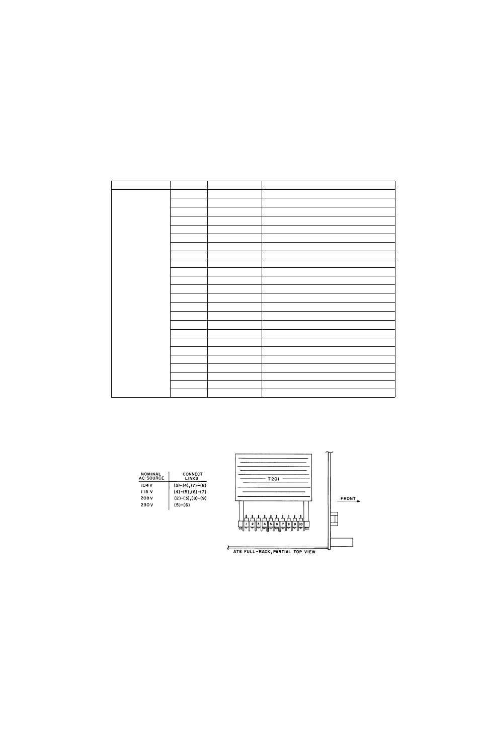
SOURCE POWER REQUIREMENTS
This power supply is normally configured for operation on a single phase, nominal 115V a-c line.
For conversion to other a-c source voltages, refer to Figure 2-4. Select your nominal source volt-
age and change the links on the barrier strip of T201 according to the table provided in Figure 2-
4. The circuit breaker (CB101) remains equally effective at all input voltages.
FIGURE 2-4. A-C INPUT SOURCE VOLTAGE SELECTION, ATE-DMG FULL RACK SERIES
TABLE 2-4. INPUT/OUTPUT PIN ASSIGNMENTS FOR REMOTE CONTROL
CONNECTOR
PIN
SIGNAL NAME
FUNCTION
IEEE 488
PORT
1
D
I
01
I/O Line
2
D
I
02
I/O Line
3
D
I
03
I/O Line
4
D
I
04
I/O Line
5
EOI
End or Identify
6
DAV
Data Valid
7
NRFD
Not Ready for Data
8
NDAC
Not Data Accepted
9
IFC
Interface Clear
10
SRQ
Service Request
11
ATN
Attention
12
SHIELD
Shield
13
D
I
05
I/O Line
14
D
I
06
I/O Line
15
D
I
07
I/O Line
16
D
I
08
I/O Line
17
REN
Remote Enable
18
GND
Ground (signal common)
19
GND
Ground (signal common)
20
GND
Ground (signal common)
21
GND
Ground (signal common)
22
GND
Ground (signal common)
23
GND
Ground (signal common)
24
LOGIC GND
Logic Ground