2 crowbar circuit, 3 user-defined voltage/current limits, 7 equipment supplied – KEPCO ATE-DMG SERIES User Manual
Page 20: 8 accessories, Table 1-6. accessories, Crowbar circuit -6, User-defined voltage/current limits -6, Equipment supplied -6, Accessories -6
1-6
ATE-DMG OPER 042314
1.6.1.2
CROWBAR CIRCUIT
An overvoltage crowbar circuit protects the load from momentary or long term overvoltages. The
crowbar conducts across the power supply output and the AC POWER SWITCH/CIRCUIT
BREAKER is tripped if such overvoltage occurs. The setting of the front panel LEVEL control
determines the threshold between the operating voltage of the power supply and the level at
which the crowbar circuit will be activated. The crowbar level is set from the front panel (refer to
PAR. 3.3). This feature is used as a hardware backup protection in case of overvoltage.
1.6.2
NON-VOLATILE STORAGE OF PROGRAMMED SEQUENCES OR ACTIVE SETTINGS
The ATE-DMG Power Supply contains 40 memory locations that can be used either to prepro-
gram a sequence of output values or to store the active settings. For programming sequences
each memory location accommodates six parameters: output voltage, output current, Overvolt-
age, Overcurrent, Time (how long the parameters are in effect) and the next address in the
sequence. Values are stored in the non-volatile memory, and are retained when the unit is
turned off. Refer to PAR. 3.4.12.
The same 40 memory locations are also available to save the active programmed settings
(V SET, I SET, OV SET and OC SET). The saved setting can be recalled by specifying the
memory location.
1.6.3
USER-DEFINED VOLTAGE/CURRENT LIMITS
The ATE-DMG output can be programmed not to exceed user-defined values. For example, the
ATE 25-40DMG, which has a maximum capacity of 25V, 40A, can be limited to 5.5V, 20A for
working with circuitry that might be damaged by higher levels. Once the limits are set, the power
supply becomes, in effect a 5.5V, 20A supply and values exceeding the limit values will not be
accepted. Refer to PAR. 3.4.11.
1.7
EQUIPMENT SUPPLIED
The unit is shipped with a standard Power Cord, 115 VAC (USA, standard configuration plug).
1.8
ACCESSORIES
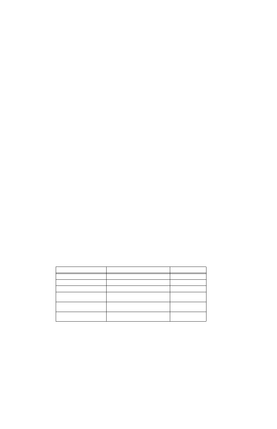
Accessories for the ATE-DMG Power Supply are listed in Table 1-6.
TABLE 1-6. ACCESSORIES
ITEM
FUNCTION
PART NUMBER
IEEE 488 Cable, (1 meter long)
Connects ATE-DMG power supply to GPIB bus
118-0916
IEEE 488 Cable, (2 meter long)
Connects ATE-DMG power supply to GPIB bus
118-0917
IEEE 488 Cable, (4 meter longs)
Connects ATE-DMG power supply to GPIB bus
118-0918
Ribbon Cable
Used for connections to Remote Analog Pro-
gramming connector A11J5 (see PAR. 3.5)
142-0246
(AMP 746285-1 )
Housing for discrete wires
Used for connections to Remote Analog Pro-
gramming connector A11J5 (see PAR. 3.5)
(Molex 22-55-2101) or
(Digikey WM2522-ND)
Pins
Used for connections to Remote Analog Pro-
gramming connector A11J5 (see PAR. 3.5)
(Molex 0016020083) or
(Digikey WM9139CT-ND)