Table 2-2. rear panel terminations, Figure 2-2. ate-dmg full rack series rear panel, Ate-dmg full rack series rear panel -3 – KEPCO ATE-DMG SERIES User Manual
Page 27: Rear panel terminations -3
ATE-DMG 042314
2-3
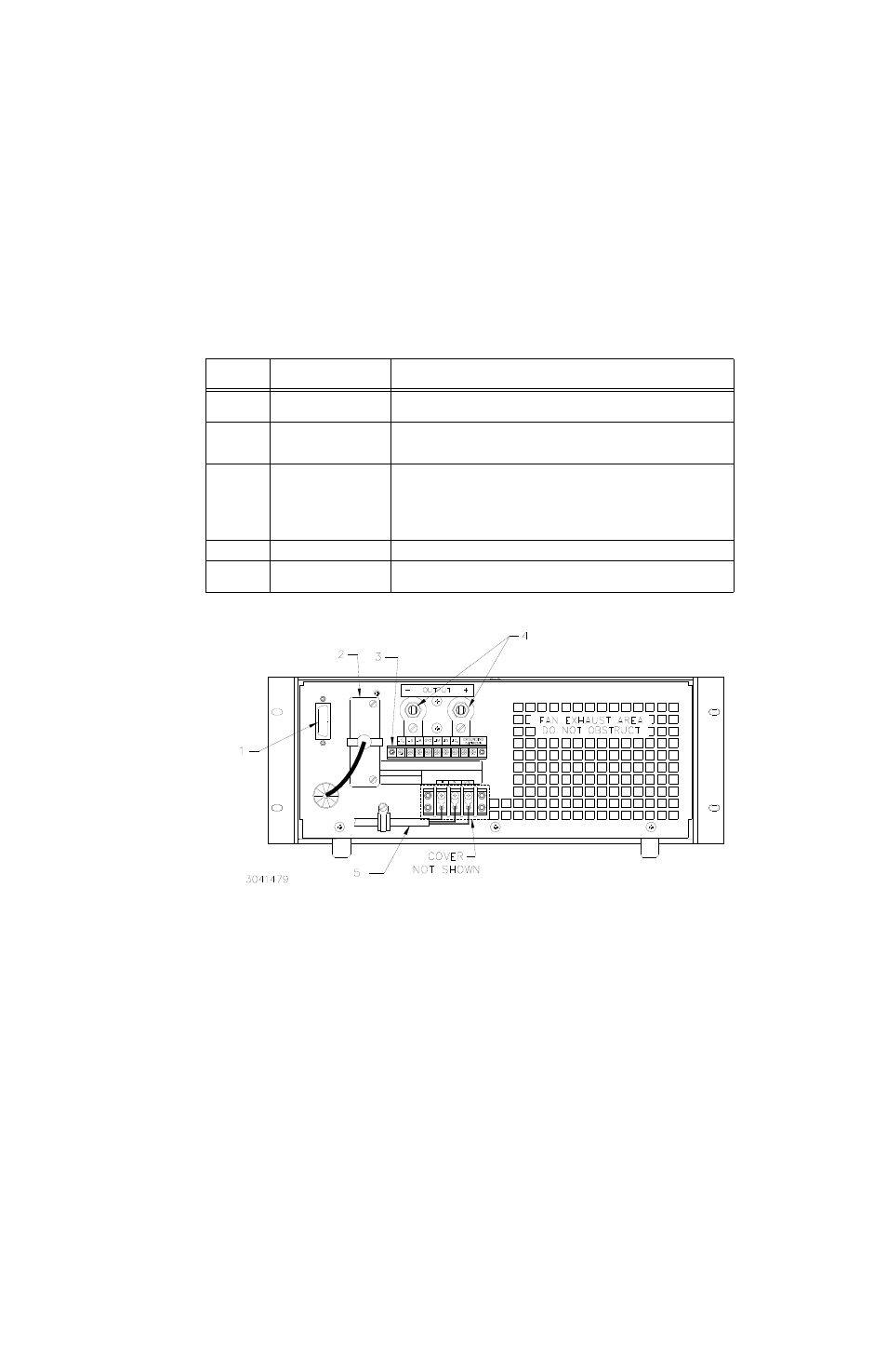
FIGURE 2-2. ATE-DMG FULL RACK SERIES REAR PANEL
TABLE 2-2. REAR PANEL TERMINATIONS
FIGURE 2-2
INDEX NO.
TERMINATION
FUNCTION
1
GPIB (IEEE 488) Interface
connector
Allows digital control of power supply and provides digital indication of status and
power supply output. See Table 2-4 for input/output pin assignments.
2
Interconnection Assembly
Used to gain access to internal circuitry for fast mode conversion, troubleshooting,
and parallel/serial connections. Can also be used with PC-12 connector (wired) for
troubleshooting.
3
Rear Panel Barrier Strip
Nine terminals provided:
1, 7: Co (–) and Co (+) used to connect external output capacitor.
2, 6: S (–) and S (+) used to connect external sensing leads.
3, 5: M (–) and (+) used for output monitor connections.
4: Ground
8, 9: Used to connect or disconnect internal grounding network (see PAR. 2.6.1.2)
4
Output terminals
Used to connect load
5
Source power terminal
block
Used to connect source power; accepts 3-wire a-c input cord (supplied).