Table 1-4. overvoltage/overcurrent settings, Ate dynamic specifications, resistive load -4, Overvoltage/overcurrent settings -4 – KEPCO ATE-DMG SERIES User Manual
Page 18: Able 1-3, Able 1-4 a
1-4
ATE-DMG OPER 042314
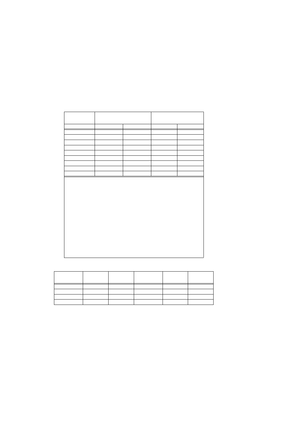
TABLE 1-3. ATE DYNAMIC SPECIFICATIONS, RESISTIVE LOAD
OUTPUT
VOLTAGE RATING
PROGRAMMING BANDWIDTH
(FAST MODE)
(KHz)
PROGRAMMING TIME CONSTANT
(FAST MODE)
sec)
Typical
minimum
Typical
maximum
6V
23.0
16.0 7.0
10.0
15V
20.0
10.6 8.0
15.0
25V
11.5
8.0 14.0
10.0
36V
8.0
6.4 20.0
20.0
55V
4.8
4.0 33.0
25.0
75V
4.3
3.5 37.0
40.0
100V
2.7
2.5 60.0
45.0
150V
1.8
1.7 88.0
95.0
325V
1.5
0.937
110.0
170.0
NOTES:
1.
VOLTAGE RECOVERY FOR A STEP-LOAD CURRENT IN FAST MODE: The time required for the stabilized output
voltage to recover to within 0.1% (10mV for ATE 75-15DMG) of the output voltage setting, for a 10 to 100% step in rated
load current is typically less than 50usec., 100usec. maximum.
2.
CURRENT RECOVERY FOR STEP-LOAD VOLTAGE IN SLOW MODE: The stabilized output current recovers from a
step in load (compliance) voltage with an exponential response, the time constant of which is determined by the load
resistance and the tabulated output capacitance (See Table 1-1).
3.
PROGRAMMING SPEED: The speed with which the power supply output responds to external programming signals is
determined by:
a) The PROGRAMMING TIME CONSTANT (
), given in the “slow” mode by either the load resistance (R
L
) and
the value of the output capacitor (C
O
, see Table 1-1):
= R
L
C
O
, or by the FEEDBACK TIME CONSTANT,
given by the product of the feedback capacitor and the feedback resistor:
= R
f
C
f
. whichever is greater. In
the “fast” mode, the PROGRAMMING TIME CONSTANT and bandwidth (-3dB) for the Voltage Control Chan-
nel is shown above.
For the Current Control Channel, the PROGRAMMING TIME CONSTANT in Fast Mode is 25usec. typical,
50usec. maximum. (80usec. for the ATE 325-0.8M).
b) The MAXIMUM RATE OF CHANGE that the power supply output can respond to in Slow Mode is given by the
setting of the power supply's current control setting (ILIM), divided by the ATE output capacitor (C
O
see Table
1-1):
MAXIMUM RATE OF CHANGE = I
LIM
/C
O
.
TABLE 1-4. OVERVOLTAGE/OVERCURRENT SETTINGS
MODEL NUMBER
MAXIMUM
OVERVOLTAGE
SETTING
MAXIMUM
OVERCURRENT
SETTING
MODEL NUMBER
MAXIMUM
OVERVOLTAGE
SETTING
MAXIMUM
OVERCURRENT
SETTING
ATE 6-100DMG
6.5V
110A
ATE 55-20DMG
60V
22A
ATE 15-50DMG
16.5V
55A
ATE 75-15DMG
82V
16A
ATE 25-40DMG
27V
44A
ATE 100-10DMG
110V
11A
ATE 36-30DMG
39V
33A
ATE 150-7DMG
165V
7.7A