3 heat trace monitoring, 1 flg temp coef setting, Heat trace monitoring -17 – Yokogawa EJX440A User Manual
Page 57: 1 flg temp coef setting -17
<4. Diagnostics>
4-17
IM 01C25T01-01E
4.2.3 Heat Trace Monitoring
The EJX with Heat trace monitoring function
calculates the flange temperature by using the two
temperature sensors built in the EJX.
An analog alert is generated if the temperature
reached to the preset level.
The flange temperature is based on the following
parameters and calculation formula.
[Parameters]
Parameter name
Explanation
Snsr temp (CT)
Measured capsule temperature
value
Amp temp (AT)
Measured amplifier temperature
value
Flg temp (FT)
Flange temperature value
(Calculated value)
Flg temp Coef (Cf)
Coefficient to calculate flange
temperature
Flg temp Hi Alert Val Threshold to generate FT high
alarm
Flg temp Lo Alert Val Threshold to generate FT low
alarm
[Calculation formula]
Flg temp (FT) = CT + Cf
f
X (CT-AT)
If the flange temperature exceeds the value preset
to
Flg temp Hi Alert Val or Flg temp Lo Alert Val,
an alert is generated.
NOTE
• The flange temperature is calculated by
the calculation formula assumed that the
capsule part of EJX is heated up or kept
warm by an electrical heater or steam. In
the case of an atmosphere temperature
or less, the difference of temperature of
approximately 3 to 4 °C, may occur because
the amplifier temperature becomes higher
than the capsule temperature.
• Use Device description (DD) file for
parameter setting.
4.2.3.1 Flg Temp Coef Setting
The value calculated according to the following
procedure is set to
Flg temp Coef.
• To enhance the calculation accuracy of the
flange temperature, measure the actual flange
temperature by using the temperature sensor
etc.
• Calculate the ratio of the capsule temperature
to the capsule temperature minus the amplifier
temperature from the two temperature values
measured by EJX.
• Derive the
Flg temp Coef from the measured
flange temperature and the ratio of the capsule
temperature to the amplifier temperature in
accordance with the following calculation
formula.
Flg temp Coef (Cf) =
(Actual measured value of Flange temperature) - CT
CT - AT
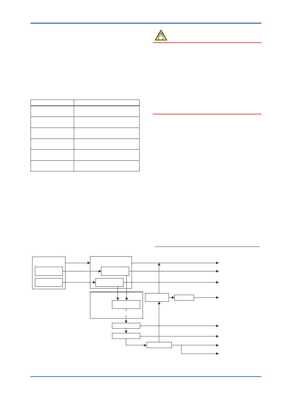
Amplifier
Temperature
Capsule
Temperature
Amp temp
Snsr temp
Flg temp Coef
Flg temp
Execution HTM
CT+(CT-AT) x Cr
Calculation of
Flg temp
Snsr temp
Flg temp
Diag Error
Display on LCD
Response Code
(Device Status)
Status group 8
Contact Output
Digital Output
Output 4-20mA
AO
Amp temp
Sensor signals
Sensor
Process Value
calculation
Alarm Masking
Result of HTM detection
HTM alarm
Result of HTM detection
DO Config
HTM alarm
HTM alarm
Diag Output
Option
F0414.ai
Figure 4.2.8 Functional Block Diagram of Heat Trace Monitoring