5 alarm and alert setting, 5 alarm and alert setting -9 – Yokogawa EJX440A User Manual
Page 49
<4. Diagnostics>
4-9
IM 01C25T01-01E
4.2.2.5 Alarm and Alert Setting
The abnormal results as the blockage detection and
high/low flange temperature (heat trace monitoring)
are given through an analog alert or the LCD
display of alarm status. Before performing the ILBD
operation, it is necessary to set the alarm and alert
according to the following procedure.
Storage of Abnormal results
(Diag Error)
Alarm Masking
(Diag Option)
Outside Diagnosis Range/
Invalid Ref xx
Masking
Alarm on
Analog Output
Alarm on
Status Output
Device Status
Field Device More Status Available
Additional Device Status
(Status group 8 and 9)
Alarm Display
on LCD
F0410.ai
Figure 4.2.5 Alarm and Alert Setting
Alarm Status
When the algorithm of ILBD and Heat trace
monitoring detect the abnormality, the result is
stored in
Diag Error. The alarm status based on the
detected abnormality is displayed to
Diag Error.
Diag Error
Bit
Alarm status
Category
0 Not used.
1 Not used.
2 A Blocking
ILBD
3 Large Fluct L
4 Large Fluct H
5 L Side Blocking
6 H Side Blocking
7 B Blocking
8 Invalid Ref F
9 Invalid Ref SPH
10 Invalid Ref SPL
11 Invalid Ref DP
12
ILBD over range
(Outside Diagnosis Range)
13 FT high alarm
Heat trace
monitoring
14 FT high alarm
15 Not used.
Note: FT indicates the flange temperature.
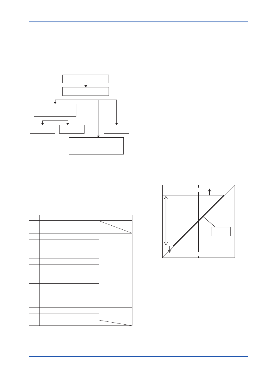
ILBD over range (Outside Diagnosis
Range)
1) Lim DPAvgmax
Lim DPAvgmax is the upper limit of the
diagnostic capability range. The limit value can
be changed when
Diag Mode is “Stop”.
DPAvg indicates the ratio of the average of
differential pressure to the EJX maximum span
regarded as 1. When
DPAvg exceeds this
limit, “ILBD over range” is generated so that the
blockage detection becomes impossible.
2) Lim DPAvgmin
Lim DPAvgmin is the lower limit of the
diagnostic capability range. The limit value can
be changed when
Diag Mode is “Stop”.
When
DPAvg is below this limit, “ILBD over
range” is generated so that the blockage
detection becomes impossible.
When the level range that can be measured by the
transmitter with 100 kPa span is –80 to 80 kPa, the
limits are set as follows.
•
Lim DPAvgmax: 0.80
•
Lim DPAvgmax: –0.80
1.000
0.000
0.80
-0.80
-1.000
Detectable
range
DPAvg
ILBD over range
ILBD over range
F0411.ai
Invalid Ref F, SPH, SPL, or DP
This alarm indicates that the reference value under
normal condition is invalid. If
Ref F is invalid, the
blockage detection excluding
BlkF is carried out.
If blockage detection function based on
BlkF is
required, obtain the reference value again.
Also when
Ref DPAvg is below Lim DPAvgmin
or exceeds
Lim DPAvgmax, all reference value
becomes invalid so that “Invalid Ref fDP”, “Invalid
Ref fSPl”, “Invalid Ref fSPh”, and “Invalid F” are
generated.