5 damping time constant setup, 6 output signal low cut mode setup, Damping time constant setup -11 – Yokogawa EJX440A User Manual
Page 21: Output signal low cut mode setup -11, Call up the pres damp display
<3. Operation>
3-11
IM 01C25T01-01E
3.4.5 Damping Time Constant Setup
The damping time constant is set as specified in
the order when the instrument is shipped. Follow
the procedure below to change the damping
time constant. The damping time constant for the
amplifier assembly can be set here. The damping
time constant for the entire transmitter is the sum
of the values for the amplifier assembly and the
capsule assembly.
Any number from 0.00 to 100.00 can be set for the
damping time constant. Note that setting the quick
response parameter ON enables you to set the time
constant between 0.00 and 0.49 seconds.
1
Call up the
Quick resp display to set the value
to less than 0.5 seconds.
EJX:YOKOGAWA
Quick resp
Off
Off
On
HELP
DEL
ESC
ENTER
Select
On and press ENTER (F4).
(ENTER)
2
EJX:YOKOGAWA
Signal condition
7 Low cut mode
8 H/L Swap Normal
9 Bi-dir mode Off
Quick resp On
T.Z. Cmp menu
HELP
SEND
HOME ENTER
Press
SEND (F2) to send the data
to the transmitter.
1. Device setup
4. Detailed setup
2. Signal condition
Quick resp
Example: To change from
2.0 seconds to 0.5 seconds
1
F0313.ai
Call up the
Pres Damp display.
EJX:YOKOGAWA
Pres Damp
2.00 sec
0.5
HELP
DEL
ESC
ENTER
Enter
0.5 and press ENTER (F4).
(ENTER)
‘0 . 5’
2
EJX:YOKOGAWA
Basic Setup
3 Re-range
4 Device information
5 Xfer fncfn
6 Pres Damp 0.50 sec
7 Low cut 10.00 %
HELP
SEND
HOME ENTER
Press
SEND (F2) to send the data
to the transmitter.
1. Device setup
3. Basic setup
6. Pres Damp
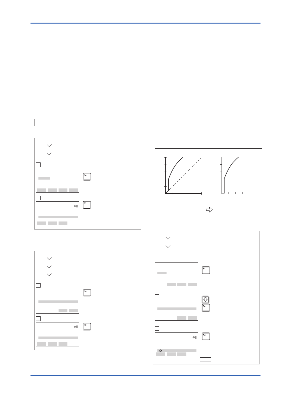
3.4.6 Output Signal Low Cut Mode Setup
Low cut mode can be used to stabilize the output
signal near the zero point.
The low cut point can be set in a range from 0 to
20%, the direct ratio corresponding to the output
signal of 4 to 20 mA. (Hysteresis for the cut point:
±10% of the cut point)
Either
LINEAR or ZERO can be selected as the low
cut mode. Unless otherwise specified, the cut mode
is set to LINEAR at the factory.
Note that when the output modes of the output
signal and the display are selected as
Sq root
and
Linear accordingly, the low cut function is not
available for the display value.
(%)
50
(%)
50
0
50
(%)
50
(%)
Output
Output
For low cut in linear mode
Input
20
20
0
For low cut in zero mode
Input
F0314.ai
Example: To set the low cut range to 20% and the cut
mode to ZERO in the
Sq root output mode,
proceed as follows:
Figure 3.4.6 Low Cut Mode
F0315.ai
EJX:YOKOGAWA
Low cut
10.00 %
10.00
HELP
DEL
ESC
ENTER
Call up
Low cut, and set to 20%.
(ENTER)
(ENTER)
‘2 0’
EJX:YOKOGAWA
Low cut mode
Linear
Linear
Zero
HELP
SEND
ESC
ENTER
Select the
Low cut mode, and
set to
Zero.
EJX:YOKOGAWA
Basic Setup
4 Device information
5 Xfer fnctn Linear
6 Pres Damp 0.50 sec
7 Low cut 20.00 %
8 Low cut mode Zero
HELP
SEND
HOME
OK
Press
SEND (F2) to send the
date, then check to confirm that
disappears.
(SEND)
1. Device setup
3. Basic setup
7. Low Cut and 8. Low cut mode
SEND
1
2
3