7 impulse line connection orientation setup, 5 detailed setup, 1 bi-directional flow measurement – Yokogawa EJX440A User Manual
Page 22: Impulse line connection orientation setup -12, Detailed setup -12 3.5.1, Bi-directional flow measurement -12
<3. Operation>
3-12
IM 01C25T01-01E
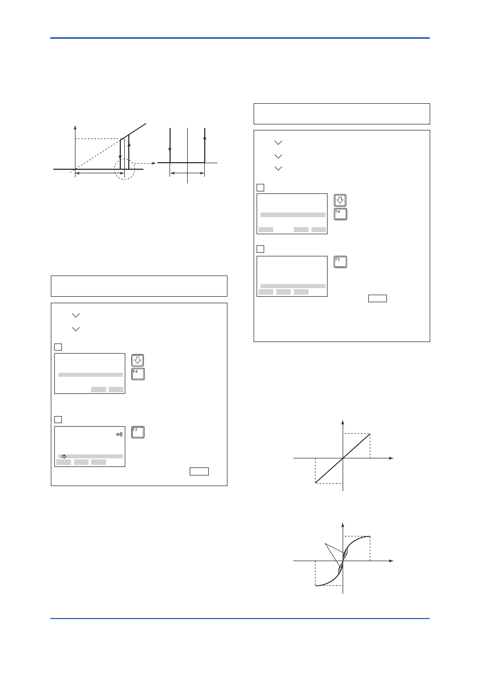
The low cut point has hysteresis so that the output
around the point is behaved as below figure.
Output mode: Linear
Low cut mode: Zero
Low cut: 20.00%
F0354.ai
Setting range: 0 to 20%
2% 2%
4mA
Output
Low cut point
Input
Hysteresis
fixed at 10%
of the cut point
7.2mA
(20%)
3.4.7 Impulse Line Connection Orientation
Setup
This function reverses the impulse line orientation.
Follow the procedure below to make this change.
F0316.ai
(ENTER)
EJX:YOKOGAWA
H/L Swap
Normal
Normal
Reverse
HELP
SEND
ESC
ENTER
Press
SEND (F2) to send the
data to the transmitter, then
check to confirm that
disappears.
(SEND)
1. Device setup
3. Basic setup
9. H/L Swap
SEND
Call up the
H/L Swap Display
Select
Reverse, and press
ENTER (F4).
EJX:YOKOGAWA
Basic setup
5 Xfer fnctn Linear
6 Pres Damp 0.50 sec
7 Low cut 20.00 %
8 Low cut mode Zero
9 H/L Swap Reverse
HELP
SEND
HOME
Example: Assign the high pressure impulse line connection
to the L side of the transmitter.
1
2
3.5 Detailed Setup
3.5.1 Bi-directional Flow Measurement
(a) Bi-dir mode enables selection of 50% output at
an input of 0 mmH
2
O.
F0317.ai
(ENTER)
EJX:YOKOGAWA
Bi-dir mode
Off
off
on
HELP
SEND
ESC
ENTER
1. Device setup
4. Detailed setup
2. Signal condition
9. Bi-dir mode
Example: If measurement range is 0 to 3000mmH
2
O
(LRV = 0 mmH
2
O, URV = 3000 mmH
2
O)
Press
SEND (F2) to send the data
to the transmitter, then check to
confirm that disappears.
Note: The measurement range changes to −3000 to 0 to
3000 mmH
2
O, corresponding the output of 0% to
50% to 100%. Note that LRV and URV values are
not changed.
(SEND)
SEND
Call up the
Bi-dir mode display
Select
on, and press ENTER (F4).
EJX:YOKOGAWA
Signal condition
5 Pres Damp 0.50 sec
6 Low cut 20.00 %
7 Low cut mode Zero
8 H/L swap Reverse
9 Bi-dir mode On
HELP
SEND
HOME
1
2
(b) Combining
Bi-dir mode with Xfer fnctn
provides a square root output computed
independently for 0% to 50% output and for
50% to 100% output.
20 mA (100% display)
4 mA (−100% display)
Output mode “LINEAR”
LRV
HRV
F0318.ai
20 mA (100% display)
Low Cut
4 mA (−100% display)
Output mode “SQUARE ROOT”
LRV
HRV