Conditions of communication line, 2 power supply voltage and load resistance, Conditions of communication line -1 – Yokogawa EJX440A User Manual
Page 10: Power supply voltage and load resistance -1
<2. Conditions of Communication Line>
2-1
IM 01C25T01-01E
2. Conditions of Communication Line
The HART communication signal is superimposed
onto the 4 to 20 mA DC analog signal. Since
the modulated wave is a communication signal,
superimposing it on the normal signal will,
from basic principles, cause no error in the DC
component of the analog signal. Thus, monitoring
can be performed via the 275 HART Communicator
while the transmitter is on-line.
2.1 Interconnection Between
DPharp and the HART
Communicator
The HART communicator can interface with the
transmitter from the control room, the transmitter
site, or any other wiring termination point in the loop,
provided there is a minimum of 250 Ω between the
connection and the power supply. To communicate,
it must be connected in parallel with the transmitter;
the connections are non-polarized. Figure 2.1
illustrates the wiring connections for direct interface
at the transmitter site for the DPharp. The HART
communicator can be used for remote access from
any terminal strip as well.
DPharp
Relaying
terminals
Distributor
Control room
Terminal
board
F0201.ai
HART
communicator
HART communicator
SUPPL
Y
PULSE
CHECK
ALARM
Figure 2.1
Connecting the HART Communicator
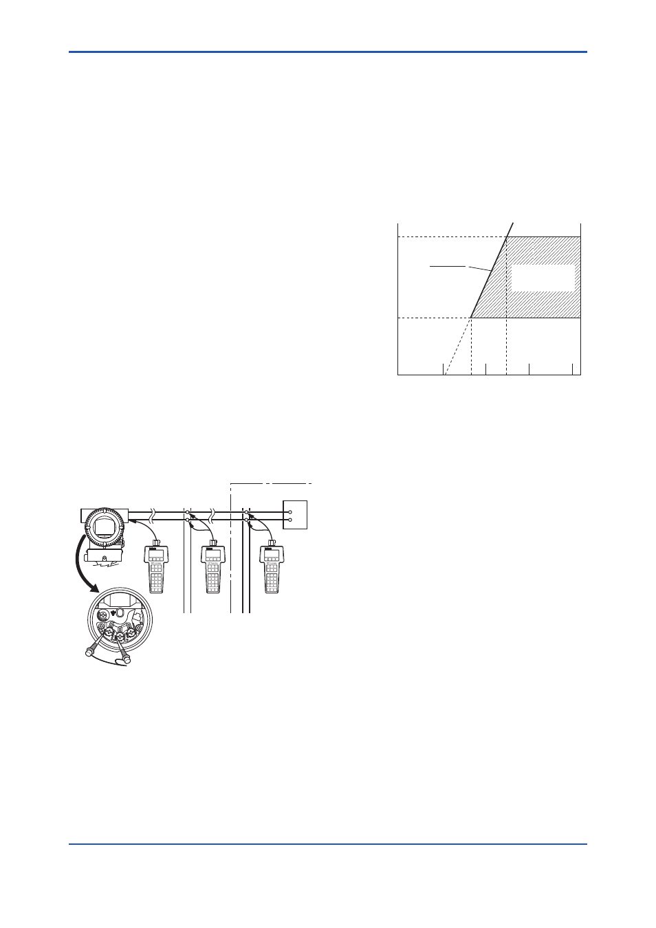
2.2 Power Supply Voltage and
Load Resistance
When configuring the loop, make sure that the
external load resistance is within the range in the
figure below.
(Note) With an intrinsically safe transmitter, external load
resistance includes safety barrier resistance.
600
250
0
10.5 16.6
25.2
42
External
load
resistance
R (Ω)
Power supply voltage E (V DC)
F0202.ai
Communication
applicable range
R= E–10.5
0.0244
Figure 2.2
Relationship between Power Supply
Voltage and External Load Resistance