2 parameter usage and selection, Parameter usage and selection -4, Important – Yokogawa EJX440A User Manual
Page 14
<3. Operation>
3-4
IM 01C25T01-01E
3.2 Parameter Usage and
Selection
Before setting a parameter, please see the following
table for a summary of how and when each
parameter is used.
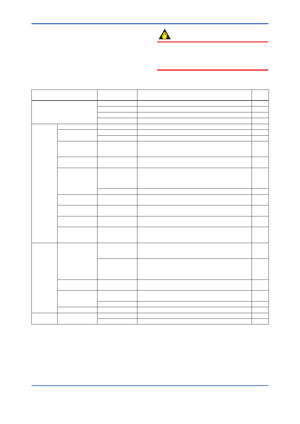
Table 3.2.1 Parameter Usage and Selection
Item
HART
communicator
Description
Page
Memory
Tag
Tag number, up to 8 characters
P.3-8
Descriptor
Up to 16 characters
P.3-8
Message
Up to 32 characters
P.3-8
Date
xx/yy/zz
P.3-8
Transmitter
Unit
Unit
Sets a pressure unit for the measured pressure
P.3-8
Range
LRV/URV
Sets the calibration range by the keypad
P.3-9
Apply values
Range for 4 to 20 mA DC signal is set with actual input applied
P.3-10
Output mode
Xfer fnctn
Sets mode for output signal to “linear mode” (proportional to
input differential pressure) or to “Square root mode” (proportional
to flow)
P.3-10
Damping time
constant
Pres Damp
Adjust the output response speed for the input pressure of
differential pressure
P.3-11
Output signal low cut
mode
Low Cut
Used mainly to stabilize output near 0 if output signal is the
square root mode. Two modes are available: forcing output to
0% for input below a specific value, or changing to proportional
output for input below a specific value
P.3-11
Low cut mode
Linear or Zero
P.3-11
Bi-directional flow
measurement mode
Bi-dir mode
Used to measure bi-directional flows
P.3-12
Unit for displayed
temperature
Temp Unit
Sets a temperature unit displayed on HART communicator
P.3-15
Unit for displayed
static pressure
SP Unit
Sets a pressure unit for the static pressure displayed on HART
communicator
P.3-16
Impulse line
connection
orientation
H/L Swap
Used where installation conditions make it imperative to
connect high pressure side impulse line to low pressure side of
transmitter
P.3-12
Display
Integral indicator
display mode
Disp Pres % fnctn
Sets mode for integral indicator to “linear mode” (proportional to
input differential pressure) or to “Square root mode” (proportional
to flow)
P.3-13
Disp select
Sets the following 5 types of integral indicator scale ranges
and unit: input pressure, % of range, user set scale, input static
pressure, % of static pressure range, and alternating among any
four of the above
P.3-14
Integral indicator
scale
Engr disp range
Sets Engr Unit/Modify Engr Unit/Engr LRV/Engr URV/Engr
point/Engr exp
P.3-13
Burst mode
Burst option
Selection of the data to be sent continuously (PV, % range/
current, or Process vars/crnt)
P.3-22
Burst mode
ON/OFF switching of burst mode
P.3-22
Process alarm
Process Alerts
Used for alarm generation on the integral indicator
P.3-27
HART output Multidrop mode
Poll addr
Sets the polling address (1 to 15)
P.3-22
Polling
ON/OFF switching of multidrop mode
P.3-23
IMPORTANT
After setting and sending data with the HART
communicator, wait 30 seconds before turning
off the transmitter. If it is turned off too soon, the
settings will not be stored in the transmitter.