Yokogawa EJX440A User Manual
Page 50
<4. Diagnostics>
4-10
IM 01C25T01-01E
NOTE
Use Device description (DD) file for parameter
setting.
Alarm Masking
Diag Option
The alarms linked to an analog alert and LCD
display are selected by
Diag Option.
The bit of
Diag Option is corresponding to that
of
Diag Error. The following alarms are set at
the factory setting, which is corresponding to
hexadecimal 0x08FC.
• A Blocking
• Large Fluct L
• Large Fluct H
• L Side Blocking
• H Side Blocking
• B Blocking
• Invalid Ref DP
To Link the alarm to an analog alert and LCD
display, follow the procedure below.
1) Set “Stop” to
Diag Mode.
2) Check each checkbox of the alarm, which is
selectable from bit 2 to 14.
Note: Set to “Calculation” after setting the parameter.
Alert Setting
Diag Out Option
When an alert regarding the impulse line blockage
or high/low flange temperature is generated, the
output value of 4-20 mA analog signal can be
changed.
Code
Mode
Function
0
Off
Keeping PV measurement. The alert
is not reflected to 4-20 mA analog
signal.
1
Burnout
The analog signal is shifted to the
value of
AO upper limit or AO lower
limit when an alert is generated.
The shifted direction follows Burnout
switch setting.
2
Fall back
The analog signal is hold to the
specific value,
Diag Fixed Out Val,
when an alert is generated.
Diag Fixed Out Val
This parameter is used when “Fall back” is selected
to
Diag Output Option.
When an alert is generated, the 4-20 mA analog
signal is held on the value specified by this
parameter.
The value can be entered within 3.6 to 21.6 mA.
Status Output for Advanced diagnostic
(option code AL)
The output of the abnormal results are applicable
for a transistor output (open collector) of an on/off
signal according to the status of high and low alarm
limits, which are values set to Limit parameters
as shown in 4.2.2.1,
Flg temp Hi Alert Val, or Flg
temp Lo Alert Val (Refer to 4.2.3.2).
DO Select
If the advanced diagnostic function is installed, the
following modes can be also assigned to the status
output in addition to Pres, SP, and Temp.
Code
Mode
Function
8
Diag Alarm
The status regarding advanced
diagnostic masked by
Diag Option
is output.
9
All
All status of Press, SP, Temp, and
advanced diagnostic are output.
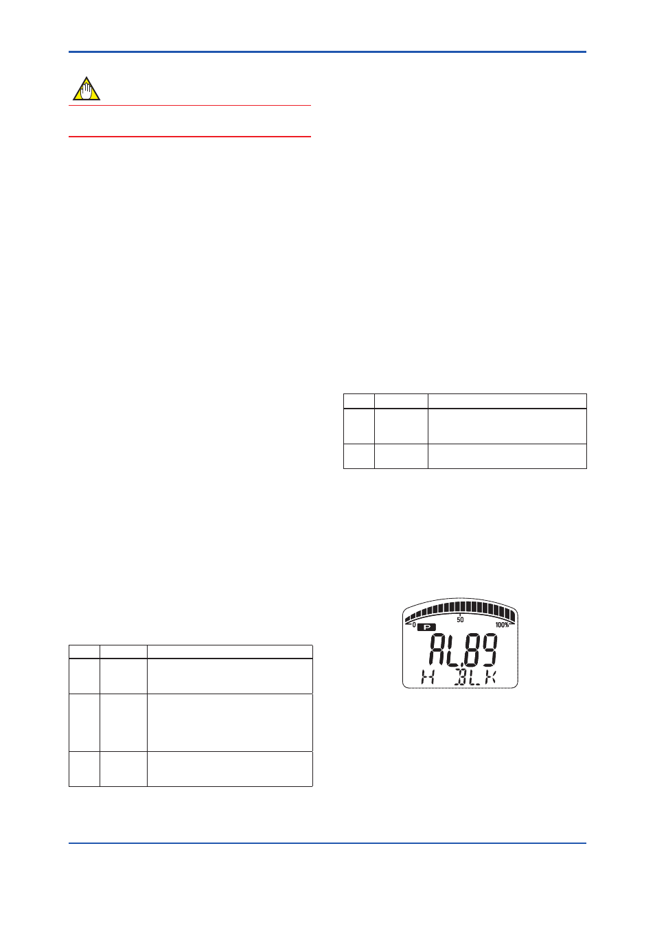
Alarm Display on LCD
If the ILBD algorithm detects the abnormality, the
content of the detected result is displayed with
“AL.88” or “AL.89” on the LCD. “AL.88” indicates
that condition is not applicable for the abnormality
detection and “AL.89” indicates the abnormality is
detected.
F0412.ai
Figure 4.2.6 Display Example of H Side Blocking
The alarm display on LCD regarding the advanced
diagnostic is described in Table 4.3.1.