9 start ilbd operation, 10 tuning, 9 start ilbd operation -13 4.2.2.10 tuning -13 – Yokogawa EJX440A User Manual
Page 53
<4. Diagnostics>
4-13
IM 01C25T01-01E
5) Check also the operation of the analog alert if
an analog alert is set.
6) Open the valve completely and check that
there are no alarms.
Simulation of Both-pressure Side
Blockage
1) Close the both-pressure-side valves.
2) Confirm the value of
Pres is stable. If not,
open the valve a little.
3) Set “Calculation” to
Diag Mode so as to start
blockage detection operation.
4) Check that an alarm of “B Blocking” is
generated after the time that consists of
Diag
Period and Diag Supp Count passed.
5) Check also the operation of the analog alert if
an analog alert is set.
6) Open the valve completely and check that
there are no alarms.
4.2.2.9 Start ILBD Operation
NOTE
Use Device description (DD) file for parameter
setting.
If process condition and capability to detect a
blockage are confirmed, you can start the ILBD
operation according to the following procedure.
1) Check the value of sampling period (
Diag
Period).
2) Check the number of times that detect the
blockage consecutively in order to give an
alarm (
Diag Supp Count). The default value
at the shipment is set to 3 times.
3) Set “Calculation” to
Diag Mode.
If the reference value has not yet been
obtained, set “Reference” to
Diag Mode.
After obtained the reference values, the
ILBD starts automatically. At the same time,
Diag Mode changes automatically from
“Reference” to “Calculation”.
4.2.2.10 Tuning
NOTE
Use Device description (DD) file for parameter
setting.
When the pressure fluctuation amplitude in fluids is
not sufficiently large or an alarm is often generated
according to the process condition, tune up by
changing the threshold for the blockage detection
(Limit parameters) or the sampling period (
Diag
Period) to enhance the accuracy of the blockage
detection The ILBD operation must be stopped to
tune up. Set “Stop” to
Diag Mode.
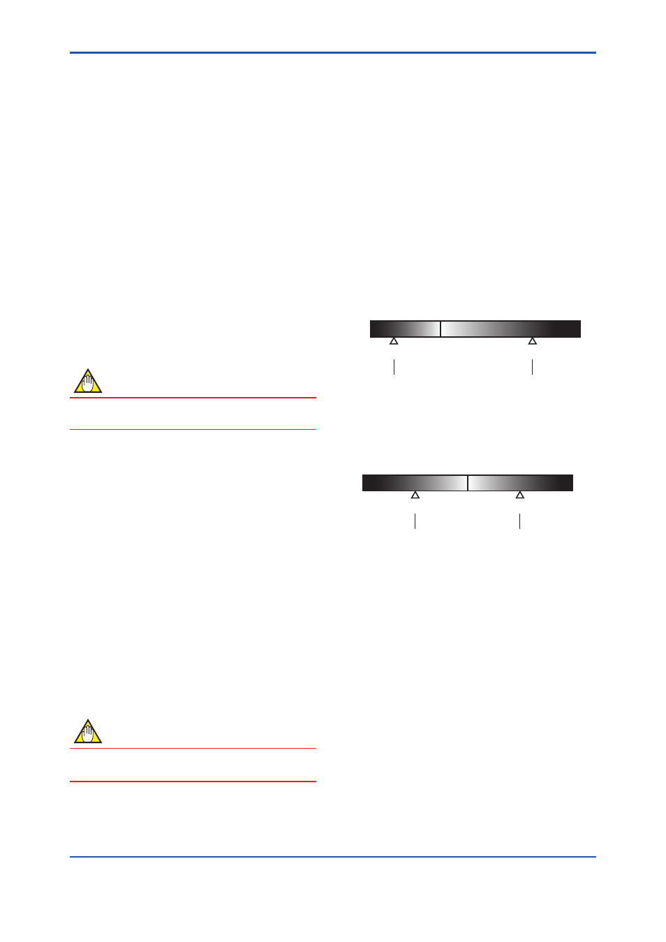
Threshold Value
The figure below shows the image of tuning effect
with a monochrome bar.
(a) The tuning image of the threshold values for
(1)
Ratio fDP: Sqrt (fDP/Ref fDP),
(2)
Ratio fSPl: Sqrt (fSPl/Ref fSPl),
(3)
Ratio fSPh: Sqrt (fSPh/Ref fSPh)
F0413-1.ai
0
1
3
Threshold (lower side)
Threshold (upper side)
(1)
Lim fDPmin
(2)
Lim fSPlmin
(3)
Lim fSPhmin
(1)
Lim fDPmax
(2)
Lim fSPlmax
(3)
Lim fSPhmax
(b) The tuning image of the threshold values for
(4) Sqrt (
BlkF/Ref BlkF)
F0413-2.ai
0
-1
1
Threshold (lower side)
Threshold (upper side)
(4)
Lim BlkFmin
(4)
Lim BlkFmax
Figure 4.2.7 Tuning Image of Threshold Value
Move the threshold toward the white.
• It becomes increasingly likely to give a false
alarm due to the disturbance from environment
change.
• If flow/differential pressure is below
Lim
DPAvgmin or exceeds Lim DPAvgmax,
pressure fluctuation is likely too small or too
large to detect the blockage.
Move the threshold toward the black.
• It enables to be insusceptible to disturbance
such as environment change and to detect the
blockage easier.
• It becomes giving an alarm of the blockage after
the blockage has been progressed.