Verdrahtung ausgang 1, 11 verdrahtung ausgang 1, Wechselstromausgänge – Watlow Series 984 User Manual
Page 21: Logikausgang
WATLOW Serie 982 Benutzerhandbuch
2.11
Installation und Verdrahtung, Kapitel 2
˜
HINWEIS:
Die fünf folgenden
Schritte garantieren
Ihnen eine erfolg-
reiche Installation:
• Überprüfung der
Typennummer und
Softwareauswahl (s.
Anhang);
• Einstellung der
DIP-Schalter (s.
Kapitel 1);
• Meßfühler-
konfiguration (s.
Kapitel 2 und
Anhang);
• Meßfühler-
installation (s.
Kapitel 2); und
• Verdrahtung (s.
Kapitel 2).
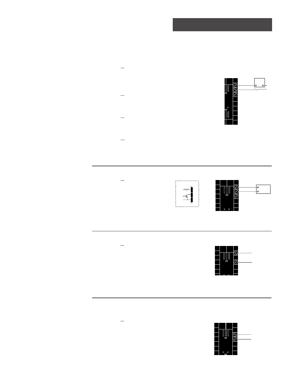
Abb. 2.11a:
Wechselstromausgänge
Halbleiterrelais
mit Filter
98 _ C - _ _ B _ - _ _ _ _
0,5 A, minimale Impedanz im AUS-Zustand: 20 k
Ω
Elektromechanisches Relais
mit Filter
(nur an NO- und COM-Kontakten)
98 _ C - _ _ D _ - _ _ _ _
Typ C, 5 A, minimale Impedanz im AUS-Zustand: 20 k
Ω
Elektromechanisches Relais
ohne Filter
98 _ C - _ _ E _ - _ _ _ _
Typ C, 5 A, Impedanz im AUS-Zustand: 31 M
Ω
Halbleiterrelais
ohne Filter
98 _ C - _ _ K _ - _ _ _ _
0,5 A, Impedanz im AUS-Zustand: 31 M
Ω
Verdrahtung Ausgang 1
Abb. 2.11b:
Logikausgang
98 _ C - _ _ C _ - _ _ _ _
Minimaler Lastwiderstand: 500
Ω
Externe
Last
COM
L1
L2
Sicherung
NO
(Schließer)
12
13
NC (Öffner)
14
(14 nur für D- und E-Ausgänge)
12
Externe
Last
+
13
14
-
COM
Abb. 2.11d:
Regelanalogausgang: 0-5 V
О
О
, 1-5 V
О
О
und 0-10 V
О
О
Gleichspannung
98 _ C - _ _ F _ - _ _ _ _
Minimaler Lastwiderstand: 1 k
Ω
Abb. 2.11c:
Regelanalogausgang: 0-20 mA und 4-20 mA
98 _ C - _ _ F _ - _ _ _ _
Maximaler Lastwiderstand: 800
Ω
14
-
+
12
14
-
+
13
+ Vdc
Innenschaltbild
12
13
14
790
Ω
19 bis 32 V
Î
(Gleichspannung)