Output 1 – Watlow MINICHEF 2000 User Manual
Page 15
S t e p 2 W i r e t h e C o n t r o l l e r
Output 1
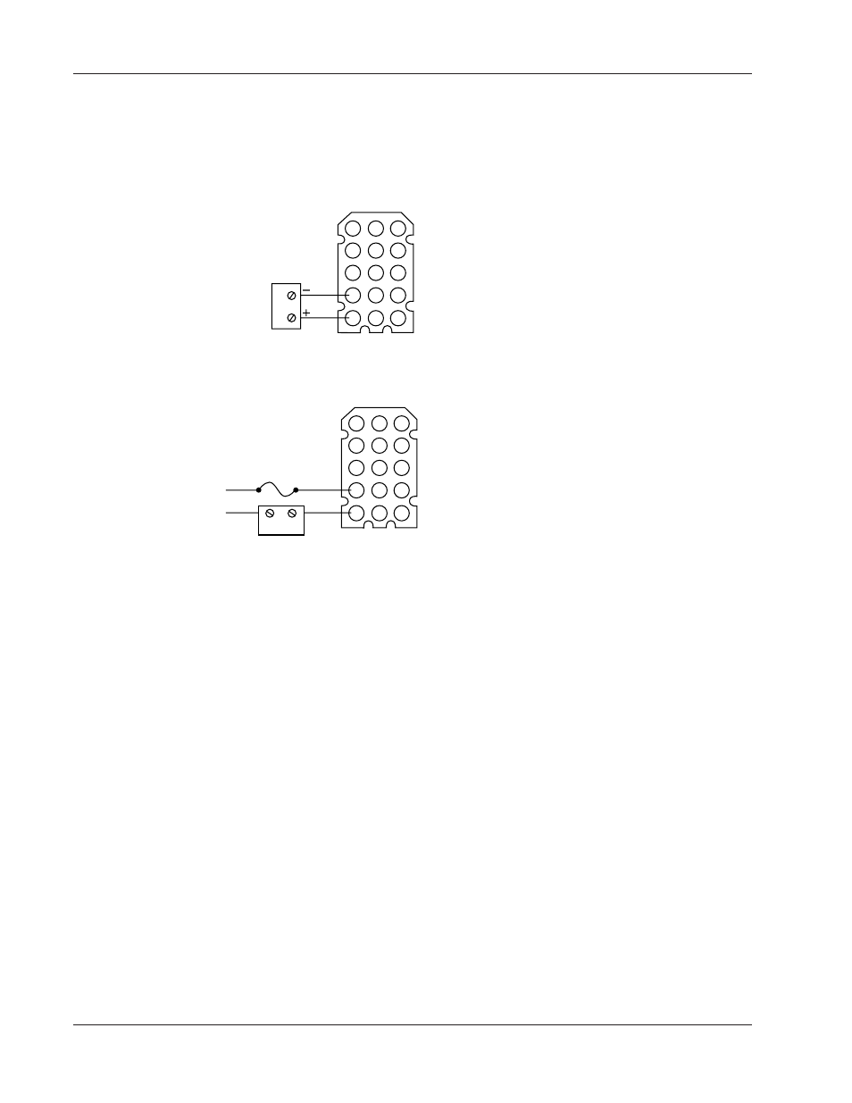
Note: The following illustrations are views of the back of the controller, not of the mating connector.
F 2 _ _ – _ 1 _ _ – _ _ _ _
Figure 14a — Switched DC Option (5V nominal, 30mA, non-isolated).
Form A, 0.4A, with or without RC Suppression
F 2 _ _ – _ 2 _ _ – _ _ _ _ (without RC Suppression)
F 2 _ _ – _ 3 _ _ – _ _ _ _ (with RC Suppression)
Figure 14b — Solid-state Relay Option.
Note: Not all software applications require Output 1. For specific information consult the application guide for the
application you are using.
1
2
3
4
1
4
5
6
7
8
9
10
11
12
13
14
15
Ext. Load
Fuse
Com
NO
L1
L2
1
2
3
4
1
4
5
6
7
8
9
10
11
12
13
14
15
Ext. Load
1 4
■
Wa t l o w M
I N I
C
H E F
2 0 0 0
H a r d w a r e & S o f t w a r e S e t u p G u i d e
See also other documents in the category Watlow Sensors:
- 12LS Controller (111 pages)
- 8LS Controller (140 pages)
- 8PID Controller (55 pages)
- Addendum to EZwarePlus (50 pages)
- ANASCAN (62 pages)
- ANASOFT (95 pages)
- ANAWIN 2 (154 pages)
- ANAWIN 3 (23 pages)
- Calibrating Watlow Series 988 Family Process Controls (19 pages)
- CAS (98 pages)
- CAS200 (124 pages)
- CLS (180 pages)
- CLS200 (251 pages)
- CLS200, MLS300 and CAS200 (92 pages)
- Control Console (12 pages)
- CPC400 (230 pages)
- DIN-A-MITE Style A (9 pages)
- DIN-A-MITE Style B (14 pages)
- DIN-A-MITE Style C (22 pages)
- DIN-A-MITE Style D (9 pages)
- DIN-Mount Adapter Instruction Sheet, Rev A (1 page)
- Dual DAC (4 pages)
- EM Gateway (28 pages)
- E-Safe Hybrid Relay Rev B (4 pages)
- E-SAFE II Hybrid Power Switch (4 pages)
- EZwarePlus Programming (264 pages)
- EZ-ZONE PM (111 pages)
- EZ-ZONE PM PID (125 pages)
- EZ-ZONE PM Express Limit (34 pages)
- EZ-ZONE PM Express (35 pages)
- EZ-ZONE PM Integrated Controller (181 pages)
- EZ-ZONE RM Limit Module Rev C (127 pages)
- EZ-ZONE RMA Modul (79 pages)
- EZ-ZONE RMC (236 pages)
- EZ-ZONE RME (124 pages)
- EZ-ZONE RMH (161 pages)
- EZ-ZONE RUI/Gateway (62 pages)
- EZ-ZONE RM-Scanner-Modul (140 pages)
- EZ-ZONE ST (97 pages)
- F4 External Event Board - Rev.B (2 pages)
- HG Series Mercury Displacement Relay (6 pages)
- LogicPro (296 pages)
- Mercury Relay or MDR Retrofit (13 pages)
- MICRODIN (24 pages)
- MICRODIN (106 pages)