Step 2 wire the controller, Power wiring, Sensor inputs 1 and 2 – Watlow MINICHEF 2000 User Manual
Page 13
S t e p 2 W i r e t h e C o n t r o l l e r
1 2
■
Wa t l o w M
I N I
C
H E F
2 0 0 0
H a r d w a r e & S o f t w a r e S e t u p G u i d e
Step 2 Wire the Controller
Position the connector with the beveled edges at the top.
Not all software applications use or require wiring to all inputs and outputs.
For specific information consult the guide for the application you are using.
Note: The following illustration is a view of the back of the controller, not of the mating connector.
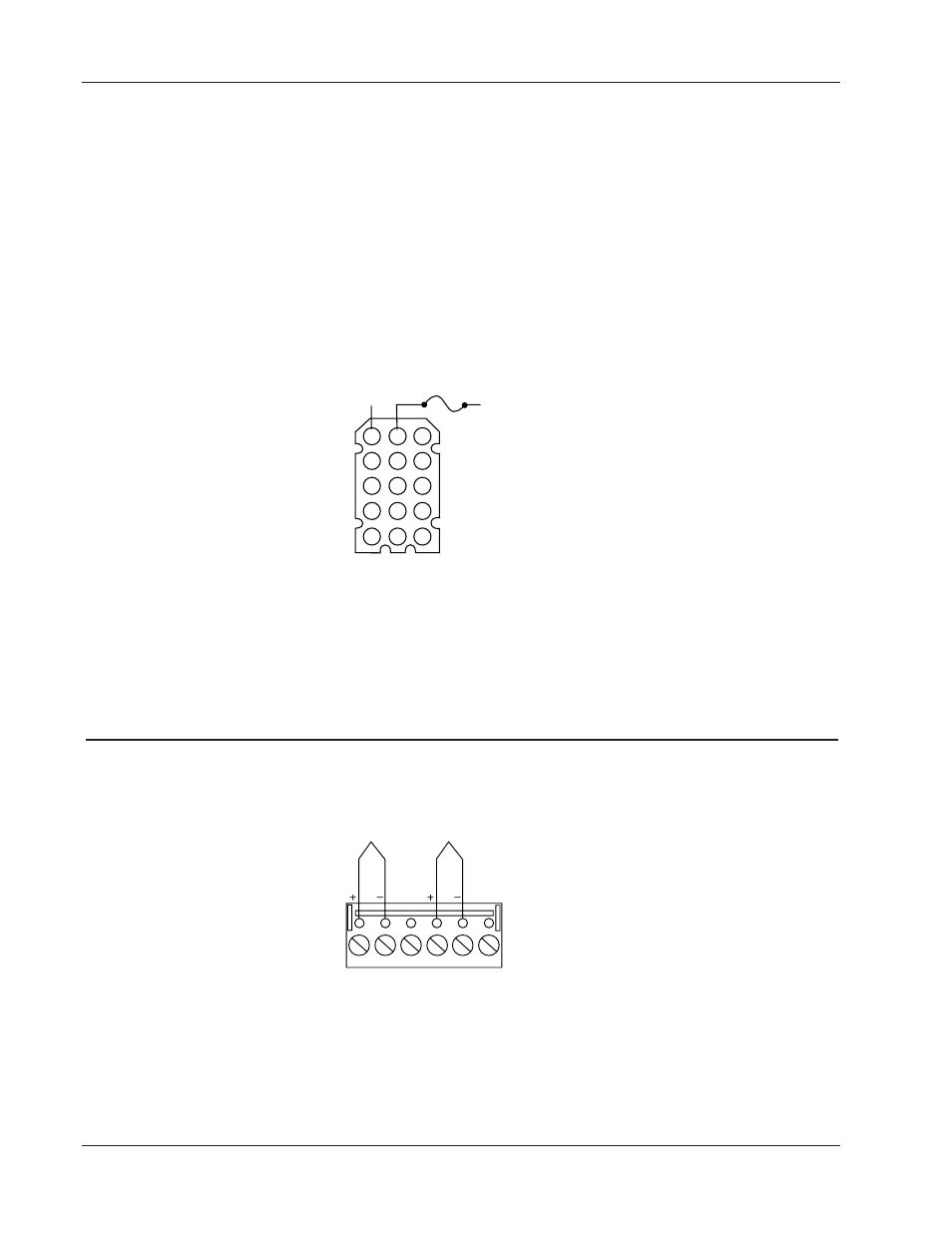
Power Wiring
Figure 12a — 24VÅ (ac) Low Voltage.
Ó
WARNING: To avoid potential electric shock, use National Electric Code (NEC) safety practices when wiring and con-
necting this unit to a power source and to electrical sensors of peripheral devices. Failure to do so could result in
injury or death.
Sensor Inputs 1 and 2
Note: The following illustrations are views of the back of the mating connector, not of the controller.
F 2 _ _ – 1 _ _ _ - _ _ _ _ (Type J, K, or E).
Figure 12b — Dual Thermocouple Option.
1
2
1
2
3
4
5
4
5
6
Input 1 Wiring
Input 2 Wiring
1
2
3
4
14
13
5
6
7
8
9
10
11
12
13
14
15
Fuse
L1
L2