Watlow Addendum to EZwarePlus User Manual
Page 33
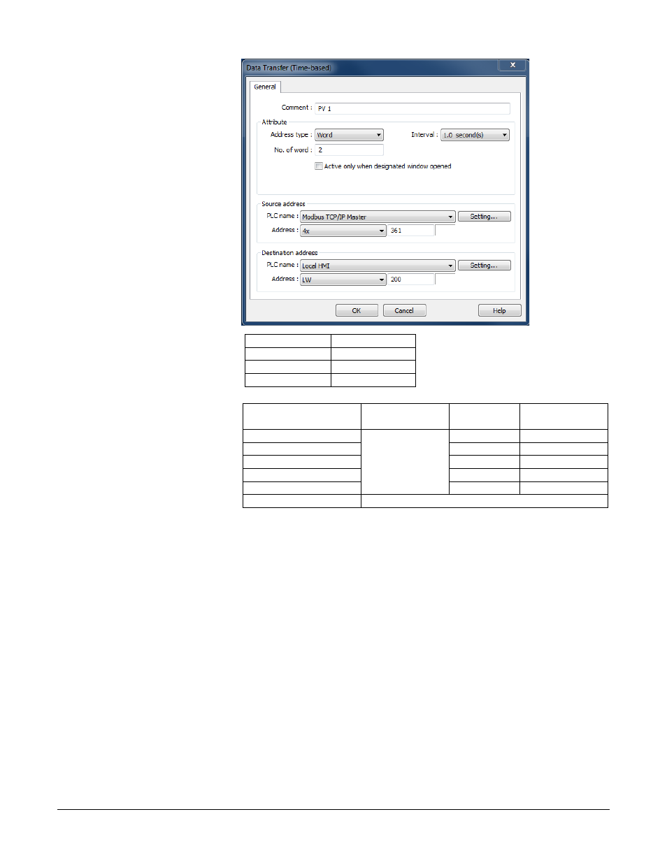
• In Comment type a
description of the data
to be copied such as
“PV 1”.
• For Address type
choose Word.
• For Interval choose a
value that is the same as
or less than the amount
of time you want
between data samples.
• In No. of words type
word size of the
parameter’s data type.
See table.
• For Source address
PLC name choose
Modbus RTU Master or
Modbus TCP/IP
Master.
• For Source address
device type choose 4x.
• In Source address
Address type the
address of the parameter
to be logged.
(042)
Data Type
No. of words
Float
2
16-bit integer
1
32-bit integer
2
For this controller…
This
parameter…
Enter this
Address*…
Choose this
Data Type…
RMCxxxx-xxxxxxx
Analog Input 1
Process Value
361
32-bit Float
RMHx-xxxx-x1xxx
381
32-bit Float
PMxxxxx-xxxxxxx
361
32-bit Float
STxx-xxMx-xxxx
20
32-bit Float
ST via RUI Gateway
361
32-bit Float
Other Controllers
Consult the controller manual.
*These addresses have already been changed to the absolute form required
for EZwarePlus by adding 1 to the value listed in the Watlow manual. Enter
them as listed.
• For Destination address PLC name choose the OIT (“Local HMI” by default).
• For Destination address device type choose LW.
• In Destination address Address type the local address at which to save the data to be logged.
Note: Pick a range of addresses with room to store all the data that must be displayed. For example, use
200 for the first parameter to be logged then for each additional parameter increment the address by
the size in words of the previous data. For example, typically you log floats such as process
variables and set points which each require two words to store. In that case if the first process
variable is copied to 200, set the next parameter to copy to 202 so on. In this example, a process
variable, a set point and the heat output power are logged.
• Click OK.
Silver Series EM OIT
33
Watlow Addendum