4 backlight inverter connectors (inv1, inv2), 5 battery connector (cn1), 6 digital i/o connector (dio1) – IEI Integration ECW-281B_D2550 User Manual
Page 96: Table 6-6: battery connector (cn1) pinouts, Table 6-7: digital i/o connector (dio1) pinouts
ECW-281B-D2550 Embedded System
Page 82
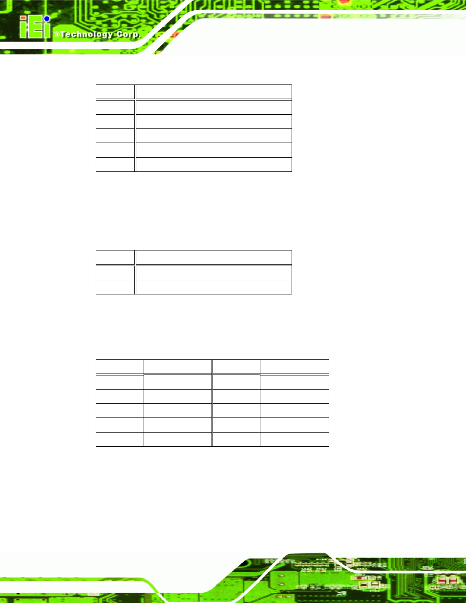
6.2.4 Backlight Inverter Connectors (INV1, INV2)
6.2.5 Battery Connector (CN1)
6.2.6 Digital I/O Connector (DIO1)
PIN NO.
DESCRIPTION
PIN NO.
DESCRIPTION
1 GND
2 VCC
3 Output
3 4 Output
2
5 Output
1 6 Output
0
7 Input
3 8 Input
2
9
Input 1
10
Input 0
PIN NO.
DESCRIPTION
1 LCD_BKLTCTL
2 GROUND
3 +12V
4 GROUND
5 LCD_BKLEN
Table 6-5: Backlight Inverter Connector (INV1, INV2) Pinouts
PIN NO.
DESCRIPTION
1 Battery+
2 GND
Table 6-6: Battery Connector (CN1) Pinouts
Table 6-7: Digital I/O Connector (DIO1) Pinouts
See also other documents in the category IEI Integration Computer Accessories:
- KM-088G (5 pages)
- ECW-281B_B2-N270 v3.01 (189 pages)
- ECW-281B_B2-N270 v2.00 (180 pages)
- ECW-281B_B2-N270 v2.10 (179 pages)
- ECW-281B_B2-D525 (137 pages)
- IBX-530B-N270 (133 pages)
- uIBX-200-VX800 v1.04 (113 pages)
- uIBX-200-VX800 v2.00 (116 pages)
- uIBX-200-VX800 v2.10 (116 pages)
- uIBX-200 v1.02 (109 pages)
- uIBX-200 v1.10 (113 pages)
- uIBX-210-CV-N2600 (163 pages)
- TANK-101B-D525_N455 v1.02 (119 pages)
- TANK-101B-D525_N455 v1.00 (118 pages)
- TANK-101B-D525_N455 v1.10 (119 pages)
- TANK-800-D525 v1.00 (116 pages)
- TANK-800-D525 v1.14 (137 pages)
- TANK-600-D2550_N2600 (132 pages)
- TANK-GM45A (104 pages)
- TANK-700-QM67 v1.00 (128 pages)
- TANK-700-QM67 v1.12 (145 pages)
- TANK-700-QM67 v2.00 (144 pages)
- TANK-720-Q67 (147 pages)
- TANK-820-H61 v1.00 (158 pages)
- TANK-820-H61 v2.00 (158 pages)
- TANK-820-H61 v2.03 (157 pages)
- TANK-6000-C226 (138 pages)
- IDS-H61 (72 pages)
- IOPS-Q67_H61 (70 pages)
- ECN-680A-H61 (190 pages)
- ECN-780-Q67 (184 pages)
- ECN-360A-HM65 (154 pages)
- ECN-360A-D2550 (141 pages)
- EBC-2102 (5 pages)
- ECN-581A-R10-HM551 (6 pages)
- EBC-3200 (6 pages)
- EBC-3100 (8 pages)
- EBC-3000 (7 pages)
- EBC-2100 (4 pages)
- EBC-3620 (8 pages)
- VSTAND (1 page)
- AUPS-C20 v1.01 (49 pages)
- AUPS-C20 v1.02 (55 pages)
- AUPS UART Protocal SPC (11 pages)