IEI Integration TANK-700-QM67 v2.00 User Manual
Tank-700, Model
TANK-700 Em b e d d e d S ys te m
P a g e i
IEI Te c h n o lo g y Co rp .
Us e r Ma n u a l
MODEL:
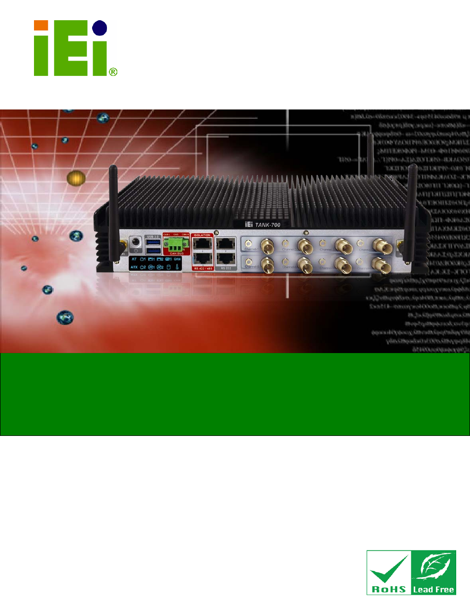
TANK-700
Hig h P e rfo rm a n c e Fa n le s s Em b e d d e d S ys te m with
In te l® 32n m CP U, On -b o a rd 2.0 GB DDR3 Me m o ry, VGA/HDMI,
US B 3.0, Du a l Co m b o (S FP Fib e r/RJ -45) Gig a b it LAN, Is o la te d
CAN-b u s , Au d io , 9V~36V DC In p u t, Ro HS Co m p lia n t
Re v. 2.00 – 28 Ap ril, 2013
Table of contents
Document Outline
- Revision
- Copyright
- Table of Contents
- List of Figures
- List of Tables
- 1 Introduction
- 2 Unpacking
- 3 Installation
- 3.1 Installation Precautions
- 3.2 Hard Disk Drive (HDD) Installation
- 3.3 Pluggable CAN-bus Terminal Block Installation
- 3.4 Pluggable DC-In Terminal Block Installation
- 3.5 Pluggable Remote Control Terminal Block Installation
- 3.6 SFP Module Installation
- 3.7 SO-DIMM Installation
- 3.8 Mounting the System with Mounting Brackets
- 3.9 External Peripheral Interface Connectors
- 3.9.1 ACC Mode Selection
- 3.9.2 AT/ATX Power Mode Selection
- 3.9.3 Audio Connector
- 3.9.4 Audio/Video Input Connectors
- 3.9.5 CAN-bus Terminal Block
- 3.9.6 Digital Input/Output Connector
- 3.9.7 HDMI Connector
- 3.9.8 LAN Connectors
- 3.9.9 Power Input, 4-pin Terminal Block
- 3.9.10 Power Input, 4-pin DIN Connector
- 3.9.11 Remote Control Connector (For AT Power Mode Only)
- 3.9.12 RJ-45 RS-232 Serial Ports
- 3.9.13 RJ-45 RS-422/485 Serial Ports
- 3.9.14 RS-232 Serial Port Connectors
- 3.9.15 SFP Fiber Connectors
- 3.9.16 USB Connectors
- 3.9.17 VGA Connector
- 3.10 Powering On/Off the System
- 3.11 Redundant Power
- 4 BIOS
- 4.1 Introduction
- 4.2 Main
- 4.3 Advanced
- 4.4 Chipset
- 4.5 Boot
- 4.6 Security
- 4.7 Exit
- A One Key Recovery
- B Safety Precautions
- C Hazardous Materials Disclosure