4 vga connector (vga1), 4 jumper settings, 1 at/atx power selection jumper (jp2) – IEI Integration ECW-281B_D2550 User Manual
Page 103: Umper, Ettings, Table 6-24: vga connector (vga1) pinouts, Table 6-25: jumpers
ECW-281B-D2550 Embedded System
Page 89
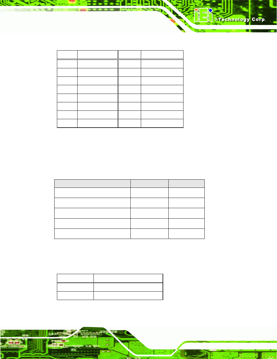
6.3.4 VGA Connector (VGA1)
PIN NO.
DESCRIPTION
PIN NO.
DESCRIPTION
1 RED
2 GREEN
3 BLUE
4 NC
5 GND
6 GND
7 GND
8 GND
9 VCC
10 GND
11 NC
12 DDC
DAT
13 HSYNC
14 VSYNC
15 DDCCLK
Table 6-24: VGA Connector (VGA1) Pinouts
6.4 Jumper Settings
The table below lists the jumpers on the ECW-281B-D2550 motherboard.
Jumper Name
Label
Type
AT/ATX power selection
JP2
2-pin header
Clear CMOS
JP3
3-pin header
LVDS1 voltage selection
JP4
3-pin header
LVDS2 voltage selection
JP1
3-pin header
LVDS2 panel type selection
SW1
DIP switch
Table 6-25: Jumpers
6.4.1 AT/ATX Power Selection Jumper (JP2)
Pin Description
Short 1-2
Use ATX power (Default)
Off
Use AT power
Table 6-26: AT/ATX Power Selection Jumper (JP2) Settings
See also other documents in the category IEI Integration Computer Accessories:
- KM-088G (5 pages)
- ECW-281B_B2-N270 v3.01 (189 pages)
- ECW-281B_B2-N270 v2.00 (180 pages)
- ECW-281B_B2-N270 v2.10 (179 pages)
- ECW-281B_B2-D525 (137 pages)
- IBX-530B-N270 (133 pages)
- uIBX-200-VX800 v1.04 (113 pages)
- uIBX-200-VX800 v2.00 (116 pages)
- uIBX-200-VX800 v2.10 (116 pages)
- uIBX-200 v1.02 (109 pages)
- uIBX-200 v1.10 (113 pages)
- uIBX-210-CV-N2600 (163 pages)
- TANK-101B-D525_N455 v1.02 (119 pages)
- TANK-101B-D525_N455 v1.00 (118 pages)
- TANK-101B-D525_N455 v1.10 (119 pages)
- TANK-800-D525 v1.00 (116 pages)
- TANK-800-D525 v1.14 (137 pages)
- TANK-600-D2550_N2600 (132 pages)
- TANK-GM45A (104 pages)
- TANK-700-QM67 v1.00 (128 pages)
- TANK-700-QM67 v1.12 (145 pages)
- TANK-700-QM67 v2.00 (144 pages)
- TANK-720-Q67 (147 pages)
- TANK-820-H61 v1.00 (158 pages)
- TANK-820-H61 v2.00 (158 pages)
- TANK-820-H61 v2.03 (157 pages)
- TANK-6000-C226 (138 pages)
- IDS-H61 (72 pages)
- IOPS-Q67_H61 (70 pages)
- ECN-680A-H61 (190 pages)
- ECN-780-Q67 (184 pages)
- ECN-360A-HM65 (154 pages)
- ECN-360A-D2550 (141 pages)
- EBC-2102 (5 pages)
- ECN-581A-R10-HM551 (6 pages)
- EBC-3200 (6 pages)
- EBC-3100 (8 pages)
- EBC-3000 (7 pages)
- EBC-2100 (4 pages)
- EBC-3620 (8 pages)
- VSTAND (1 page)
- AUPS-C20 v1.01 (49 pages)
- AUPS-C20 v1.02 (55 pages)
- AUPS UART Protocal SPC (11 pages)