IEI Integration TANK-820-H61 v2.03 User Manual
Model
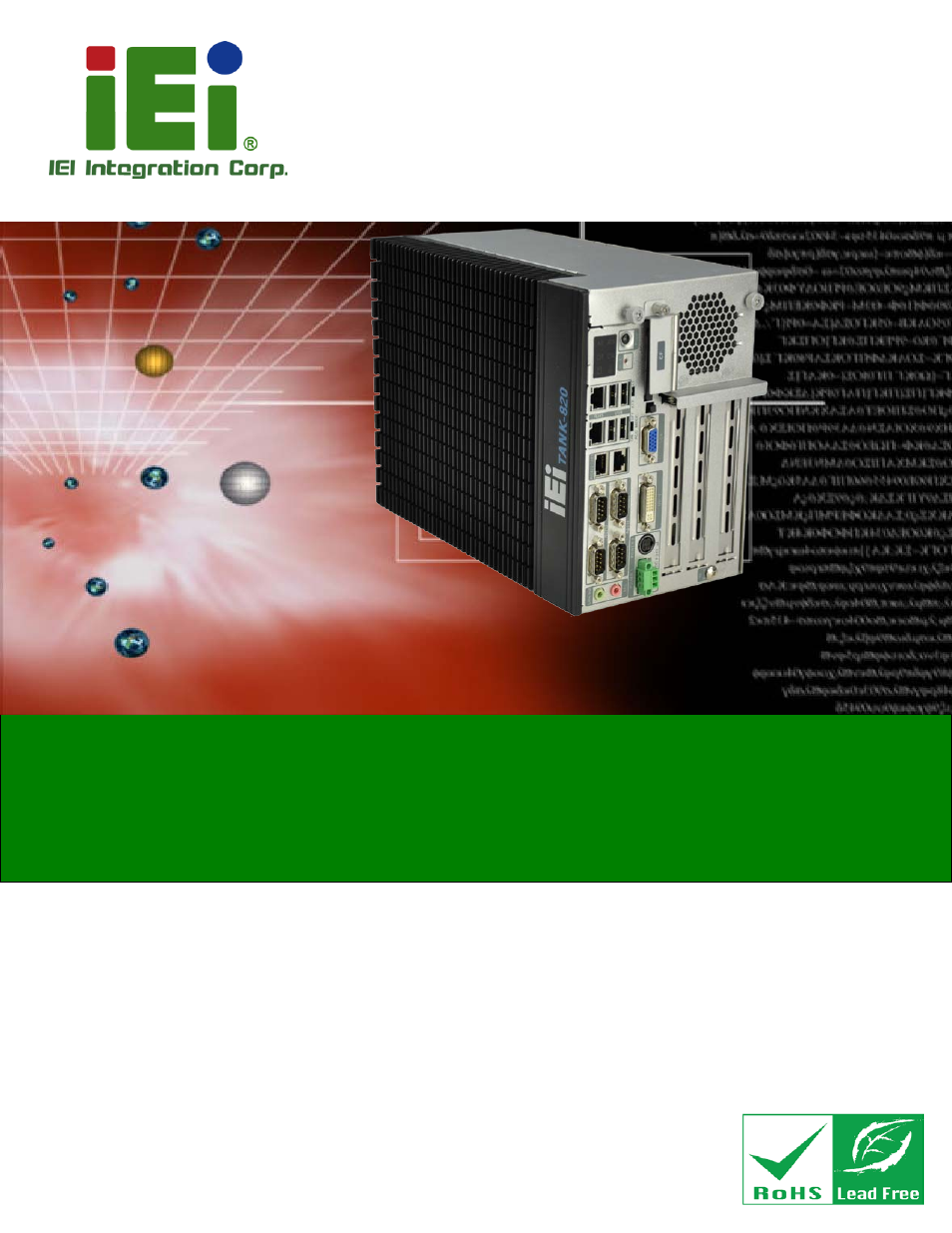
TANK-820-H61 Em b e d d e d S ys te m
P a g e i
Us e r Ma n u a l
MODEL:
TANK-820-H61 S e rie s
Em b e d d e d S ys te m with 2n d Ge n e ra tio n In te l® Co re ™ d e s kto p
p ro c e s s o r, VGA, DVI-I, Two Gig a b it Eth e rn e t,
Fo u r US B 2.0, Two US B 3.0, RS -232/422/485,
Ro HS Co m p lia n t
Re v. 2.03 – 27 De c e m b e r 2013
Table of contents
Document Outline
- Revision
- Copyright
- Table of Contents
- List of Figures
- List of Tables
- 1 Introduction
- 2 Unpacking
- 3 Installation
- 3.1 Installation Precautions
- 3.2 CF Card Installation
- 3.3 Hard Disk Drive (HDD) Installation
- 3.4 System Fan Installation
- 3.5 Mounting the System with Mounting Brackets
- 3.6 Foot Pad Installation
- 3.7 External Peripheral Interface Connectors
- 3.7.1 ACC Mode Selection
- 3.7.2 AT/ATX Power Mode Selection
- 3.7.3 Audio Connector
- 3.7.4 CompactFlash® Type II
- 3.7.5 Digital Input/Output Connector
- 3.7.6 DVI Connector
- 3.7.7 LAN Connectors
- 3.7.8 Power Input, 3-pin Terminal Block
- 3.7.9 Power Input, 4-pin DIN Connector
- 3.7.10 RJ-45 RS-422/485 Serial Ports
- 3.7.11 RS-232 Serial Port Connectors
- 3.7.12 USB Connectors
- 3.7.13 VGA Connector
- 3.8 Powering On/Off the System
- 3.9 Power
- 4 System Motherboard
- 4.1 Overview
- 4.2 Internal Peripheral Connectors
- 4.2.1 Battery Connector (BAT1)
- 4.2.2 BIOS Programming Connector (SPI2)
- 4.2.3 CPU Fan Connector (CPU_FAN1)
- 4.2.4 EC Debug Connector (CN4)
- 4.2.5 EC Programming Connector (JSPI1)
- 4.2.6 LED Connector (J2)
- 4.2.7 PCH Fan Connector (PCH_FAN)
- 4.2.8 SATA 3Gb/s Drive Connectors (SATA1)
- 4.2.9 SATA Power Connector (CN1)
- 4.2.10 SMBus Connector (CN3)
- 4.2.11 TPM Connector (TPM1)
- 4.3 External Interface Panel Connectors
- 4.3.1 Audio Jack (JAUDIO1)
- 4.3.2 DIO connector (DIO1)
- 4.3.3 DVI Connector (DVI_1)
- 4.3.4 Ethernet and USB2.0 Connectors (USBLAN1)
- 4.3.5 Ethernet and USB2.0 Connectors (USBLAN2)
- 4.3.6 Power Connector (PWR2)
- 4.3.7 Power Connector (PWR1)
- 4.3.8 RS-232 Serial Port Connector (COM1)
- 4.3.9 RS-232 Serial Port Connector (COM2)
- 4.3.10 RS-232 Serial Port Connector (COM7)
- 4.3.11 RS-232 Serial Port Connector (COM8)
- 4.3.12 RS-422/485 Serial Port Connectors (LANCOM3)
- 4.3.13 USB 3.0 Connectors (USB3_12)
- 4.3.14 VGA Connector (VGA1)
- 4.4 Jumper Settings
- 5 BIOS
- 5.1 Introduction
- 5.2 Main
- 5.3 Advanced
- 5.3.1 ACPI Settings
- 5.3.2 RTC Wake Settings
- 5.3.3 Trusted Computing
- 5.3.4 CPU Configuration
- 5.3.5 SATA Configuration
- 5.3.6 Intel TXT(LT) Configuration
- 5.3.7 USB Configuration
- 5.3.8 F81216 Secondary Super IO Configuration
- 5.3.9 F81866 Super IO Configuration
- 5.3.10 F81866 H/W Monitor
- 5.3.11 Serial Port Console Redirection
- 5.3.12 iEi Feature
- 5.4 Chipset
- 5.5 Boot
- 5.6 Security
- 5.7 Exit
- A One Key Recovery
- B Safety Precautions
- C Hazardous Materials Disclosure