9 power-on procedure, 1 installation checklist, Ower – IEI Integration ECW-281B_D2550 User Manual
Page 55: Rocedure, Figure 3-33: vga connector, Table 3-10: vga connector pinouts, See figure 3-33, Table 3-10, 1 installation checklist warning
ECW-281B-D2550 Embedded System
Page 41
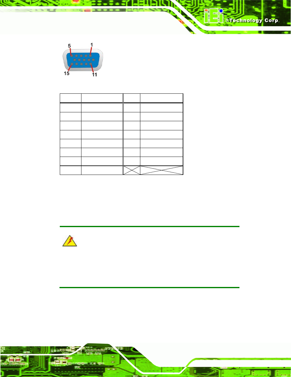
Figure 3-33: VGA Connector
Pin Description Pin
Description
1 RED
2
GREEN
3 BLUE
4
NC
5 GND
6
GND
7 GND
8
GND
9 VCC
10
GND
11 NC
12
DDC
DAT
13 HSYNC
14
VSYNC
15 DDCCLK
Table 3-10: VGA Connector Pinouts
3.9 Power-On Procedure
3.9.1 Installation Checklist
WARNING:
Make sure a power supply with the correct input voltage is being fed into
the system. Incorrect voltages applied to the system may cause damage to
the internal electronic components and may also cause injury to the user.
To power on the embedded system please make sure of the following:
The bottom surface panel is installed
All peripheral devices (VGA monitor, serial communications devices etc.) are
connected
See also other documents in the category IEI Integration Computer Accessories:
- KM-088G (5 pages)
- ECW-281B_B2-N270 v3.01 (189 pages)
- ECW-281B_B2-N270 v2.00 (180 pages)
- ECW-281B_B2-N270 v2.10 (179 pages)
- ECW-281B_B2-D525 (137 pages)
- IBX-530B-N270 (133 pages)
- uIBX-200-VX800 v1.04 (113 pages)
- uIBX-200-VX800 v2.00 (116 pages)
- uIBX-200-VX800 v2.10 (116 pages)
- uIBX-200 v1.02 (109 pages)
- uIBX-200 v1.10 (113 pages)
- uIBX-210-CV-N2600 (163 pages)
- TANK-101B-D525_N455 v1.02 (119 pages)
- TANK-101B-D525_N455 v1.00 (118 pages)
- TANK-101B-D525_N455 v1.10 (119 pages)
- TANK-800-D525 v1.00 (116 pages)
- TANK-800-D525 v1.14 (137 pages)
- TANK-600-D2550_N2600 (132 pages)
- TANK-GM45A (104 pages)
- TANK-700-QM67 v1.00 (128 pages)
- TANK-700-QM67 v1.12 (145 pages)
- TANK-700-QM67 v2.00 (144 pages)
- TANK-720-Q67 (147 pages)
- TANK-820-H61 v1.00 (158 pages)
- TANK-820-H61 v2.00 (158 pages)
- TANK-820-H61 v2.03 (157 pages)
- TANK-6000-C226 (138 pages)
- IDS-H61 (72 pages)
- IOPS-Q67_H61 (70 pages)
- ECN-680A-H61 (190 pages)
- ECN-780-Q67 (184 pages)
- ECN-360A-HM65 (154 pages)
- ECN-360A-D2550 (141 pages)
- EBC-2102 (5 pages)
- ECN-581A-R10-HM551 (6 pages)
- EBC-3200 (6 pages)
- EBC-3100 (8 pages)
- EBC-3000 (7 pages)
- EBC-2100 (4 pages)
- EBC-3620 (8 pages)
- VSTAND (1 page)
- AUPS-C20 v1.01 (49 pages)
- AUPS-C20 v1.02 (55 pages)
- AUPS UART Protocal SPC (11 pages)