Getting started manual – Teledyne LeCroy WaveSurfer MXs-B Getting Started Manual User Manual
Page 39
Getting Started Manual
922172-00 Rev A
31
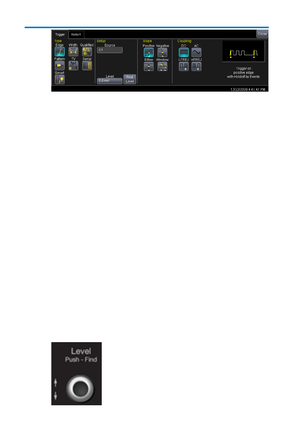
2. Touch inside the Source field in the Setup section and select an
input from the pop-up menu:
C1 through C4 are abbreviations for Channel 1 through Channel 4.
Ext and Ext/10 allow triggering on the External Input of the
oscilloscope. Ext input is +/-0.5V. Ext/10 input is+/-5.0V.
Line is for triggering on the Positive or Negative excursion of the AC
power line (not available when using battery or DC input power).
3. Select a trigger coupling from the Coupling section. Coupling refers
to the type of signal coupling at the input of the trigger circuit. You
can choose from these coupling types:
DC - All the signal’s frequency components are coupled to the trigger
circuit for high frequency bursts or where the use of AC coupling
would shift the effective trigger level.
AC - The signal is capacitively coupled. DC levels are rejected, and
frequencies below 50 Hz are attenuated.
LFREJ - The signal is coupled through a capacitive high-pass filter
network, DC is rejected and signal frequencies below 50 kHz are
attenuated. For stable triggering on medium to high frequency
signals.
HFREJ - Signals are DC coupled to the trigger circuit, and a low-pass
filter network attenuates frequencies above 50 kHz (which is used for
triggering on low frequencies).
4. Change the trigger Level by adjusting the front panel trigger level
knob.