4 wiring diagram, 68 7. speci ¿ cations – IAI America IX-UNN3515 User Manual
Page 74
68
7. Speci
¿ cations
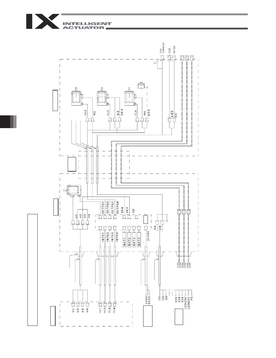
Wiring/Pipin
g Diagram (Arm Length:
300/350)
Notes
(1)
The actual layout of board conn
ec
tors varies from t
h
is drawing.
(2)
Since the brake
power circuit is
provided on the p
rimary side (high-voltage
side), a dedicated 24 V po
wer supply is
required fo
r this circuit. The 24 V power supply for
I/O circuits used on the secondary
side (low-voltage side) cannot be
shared.
(3)
To operate the al
arm LED, the
user must provide
a circuit that uses the controller I/
O output signal.
Co
n
tro
lle
r
Br
ake p
o
wer
terminals
User wiring
te
rmin
a
ls
Inside bas
e
Fle
xib
le
cable
Inside ar
m
2
Cable fix c
a
p
(C
apcon)
M
cable (
o
utside
r
obo
t)
PG
ca
bl
e
(o
u
tsid
e
ro
b
ot)
BK p
o
wer
cabl
e (
o
u
tside r
o
b
o
t)
U cable (o
utside
rob
o
t)
S
e
rvo
mo
to
r f
o
r
axis 1 (arm 1)
FG (
T
o bas
e)
A
ir joint, red (
4)
PG ca
ble (
inside
r
obo
t)
M cable (insid
e rob
o
t)
U cable (insid
e rob
o
t)
D-s
ub
co
nne
ct
o
r fo
r us
er
wiri
n
g (
1
5
-p
in,
so
cke
t)
Br
ake-
release swit
ch
f
o
r
axes 3/
4
(Z/
R-
a
xes)
Air joint, whit
e (
4)
Air joint, bl
ack (
4)
PG ca
ble (
o
u
tside r
o
bo
t)
S
e
rvo
mo
to
r f
o
r
axis 2 (arm 2)
Se
rvo
mo
to
r with
b
ra
k
e
fo
r a
x
is 3 (Z-a
xis)
S
e
rvo
mo
to
r wit
h
b
ra
k
e
fo
r a
x
is 4 (R-a
xis)
FG (
to D-
sub
ho
using)
A
la
rm L
E
D
Air joiznt, bl
ack (
4)
A
ir jo
in
t, re
d (
4)
A
ir joint, whit
e (
4)
Electr
omag
netic
br
ake f
o
r axis 4
(R-a
xis)
Boar
d
PG
ca
bl
e
(o
u
tsid
e
ro
b
ot)
7.4 Wiring
Diagram