3 installing the robot, Warning 4.2 installing the robot, Caution 4.3 – IAI America IX-UNN3515 User Manual
Page 27
21
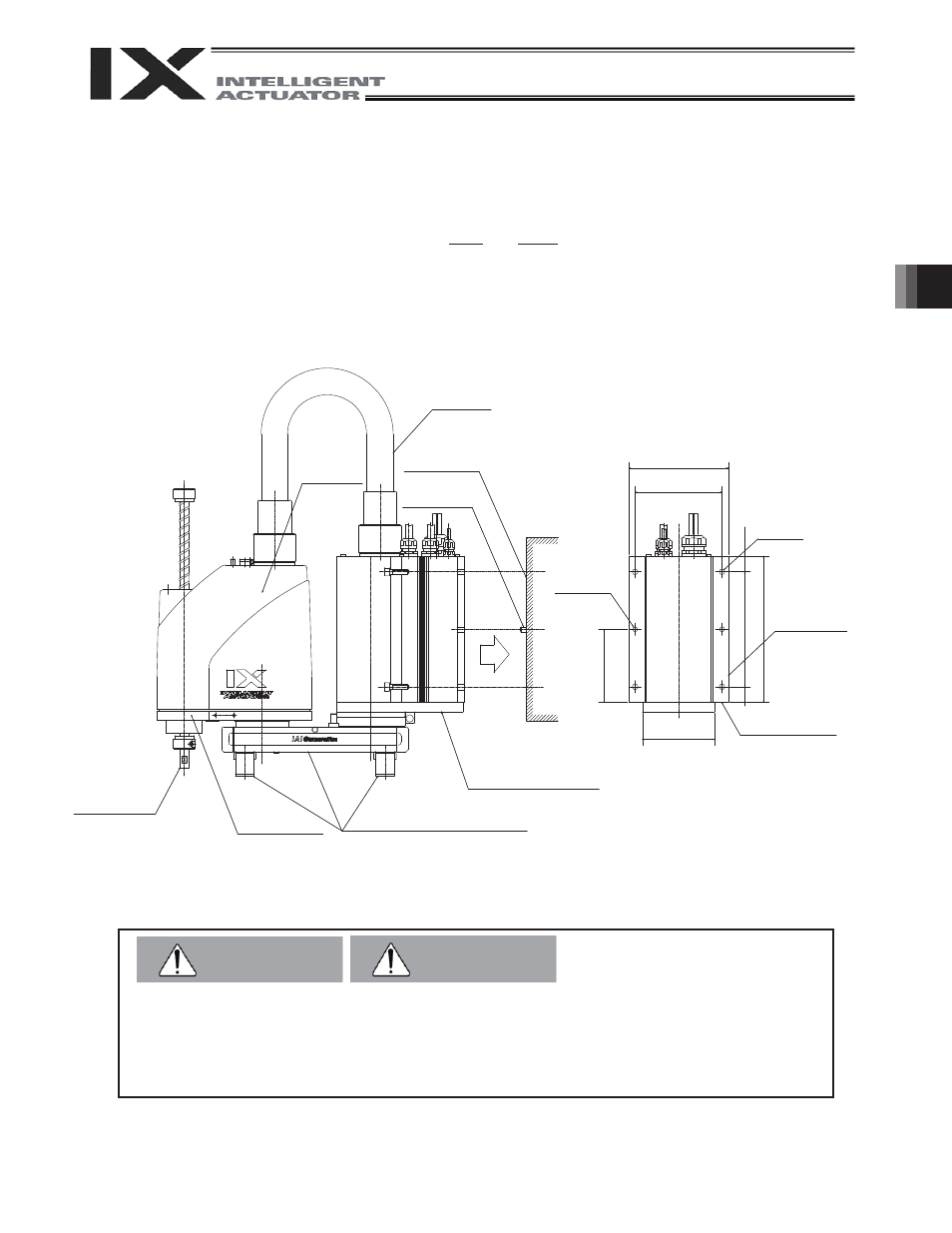
4. How to Install
Warning
4.2 Installing
the
Robot
x The base mounting surface has two Ø8H10 reference holes. Use these holes to prevent the machine
from dropping during installation and also as guides for rough positioning. (To determine the precise
position of the robot, use the base reference surface as a guide.)
x When installing the robot, support it with the base and arm 1 with arms 1 and 2 extended, and affix onto
the mounting surface.
* Be careful not to apply forces on the rotational axis and arm 2 cover during the above operation.
x Secure the robot using M8 hex bolts and washers (tightening torque: 3.2 kgfm).
For the hex bolts, use high-tension bolts with an ISO rating of 10.9 or higher.
* The inverse specification is mounted upside down.
z Be careful not to apply forces on the rotational axis, flexible tube and arm 2 cover during the
above operation. (It may cause machine problems due to bending, deformation, etc.)
z Tighten the hex bolts securely to the correct torque. Improperly tightened bolts may reduce the
accuracy of robot operation, and in the worst case cause the robot to detach and fall.
Reference
surface
Arm 2
Reference surface
2 -
I 8H10
4 -
I 9
160
140
117.5
116
235
25 185
(25)
Flexible tube
Arm 2
cover
Mounting wall
Positioning
pin
Rotational axis
Supports (arm 1)
Support (base)
Caution
4.3