IAI America IX-UNN3515 User Manual
Page 68
62
7. Speci
¿ cations
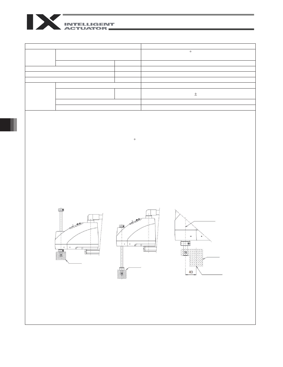
(Fig. 3)
Top position
Center of
rotational axis
Tool’ s center
of gravity
(Fig. 1)
(Fig. 2)
Tool
Bottom
position
Tool
Tool
s
n
o
i
t
a
c
i
f
i
c
e
p
S
m
e
t
I
Surrounding air temperature/humidity
Temperature: 0 to 40 C, humidity: 20 to 85%RH or
less (non-condensing)
Operating
environment
s
s
e
l
r
o
0
0
0
,
1
m
e
d
u
t
i
t
l
A
1
7
B
d
e
s
i
o
N
Robot weight
kg
21.9
Power supply
230 V 50/60 Hz
5A
Allowable supply voltage
fluctuation
%
10
Overvoltage category (IEC60664-1)
Category III
Controller
3
e
e
r
g
e
d
n
o
i
t
u
ll
o
P
)
1
-
4
6
6
0
6
C
E
I
(
e
e
r
g
e
d
n
o
i
t
u
ll
o
P
*1: To move the robot horizontally at high speed, perform teaching so that the vertical axis stays as close to
the top position as possible. (Fig. 1)
To operate the robot with its vertical axis at the bottom position, the speed and acceleration must be
reduced as appropriate. (Fig. 2)
*2: Assuming PTP instruction operation.
*3: When surrounding air temperature is fixed at 20 C.
*4: When 2 kg is carried at the maximum speed
*5: A force as much as three times the dynamic push force may apply momentarily.
*6: Static thrust indicates a thrust force that applies within the range of operation when a PAPR command is
issued.
*7: The permissible moment of inertia converted to a value at the rotational center of axis 4. The offset from
the rotational center of axis 4 to the tool’ s center ofgravity is assumed to be 40 mm or less. (Fig. 3) If the
gravity-center position of the tool is away from the center position of axis 4, the speed and/or acceleration
must be lowered as deemed appropriate.
*8: To enable the alarm LED indicator, the user must provide a circuit that supplies 24 VDC to the LED
terminal in the user connector in response to the controller I/O output signal, etc.
Design reference regulation: Machinery Directive Annexl, EN292-1, EN292-2, EN1050, EN60204-1 and EN775
Brake power source for main unit
W
24V DC ±10%
20W