Caution – IAI America IX-UNN3515 User Manual
Page 40
34
6. Inspection/Maintenance
6.2.2
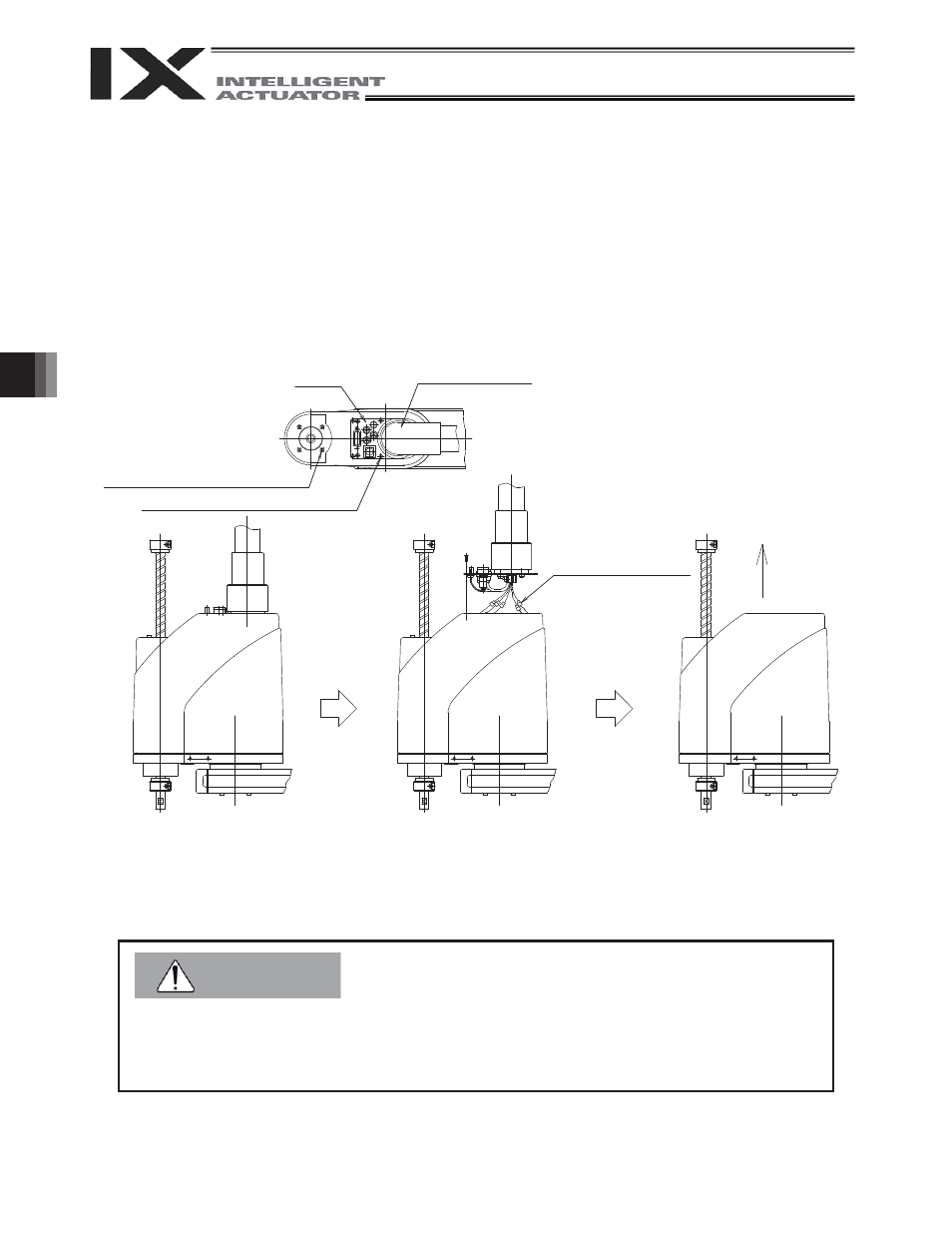
Removing the Cover
(1) With arms 1 and 2 extended as illustrated below, remove the four low-head cap screws [2] and six
countersunk head screws [1] one by one.
(2) Lift the panel and remove the motor connectors (M, PG and BK) from the back of the panel. (Do not cause
the wires to be pulled with excessive force when lifting the panel.)
(3) Lift the cover upward and remove.
z When the cover is removed, absolute reset need be performed on arm 2, rotational axis and
vertical axis. (Refer to 6.4, “Absolute Reset Method.”)
z Do not cause the wires to be pulled with excessive force when lifting the panel.
Rotary joint
[1] 6 - M3 x 4 (countersunk head screw)
Panel
Remove the motor
connectors.
Lift the cover
upward and
remove.
[2] 4 - M3 (low-head cap screw)
Caution