Caution – IAI America IX-UNN3515 User Manual
Page 45
39
6. Inspection/Maintenance
6.2.8
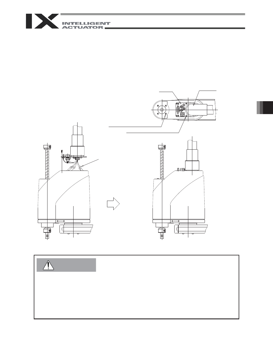
Installing the Cover
(1) Install the cover and connect the motor connectors extending from the rotary joint.
(2) Affix the panel using the six countersunk head screws [1] by paying attention not to cause the wires to rest
on top of one another.
(Place the wires neatly in the upper space without letting them rest on top of one another. Do not forcibly
tighten the screws with the panel still floating.)
(3) Tighten the four low-head cap screws [2].
z Check the marking tubes to prevent improper connections.
z Be careful not to bend the air tubes.
z Be careful not to pinch the cables.
z Place the wires neatly in the upper space without letting them rest on top of one another. Do not
forcibly tighten the screws with the panel still floating.
z Check if the connectors are fully inserted.
z When the cover is removed, absolute reset need be performed on arm 2, rotational axis and
vertical axis. (Refer to 6.4, "Absolute Reset Method.")
Connect the motor
connectors.
Rotary joint
[1] 6 - M3 x 4 (countersunk head screw)
Panel
[2] 4 - M3
(low-head cap screw)
Caution