Caution warning – IAI America IX-UNN3515H User Manual
Page 42
36
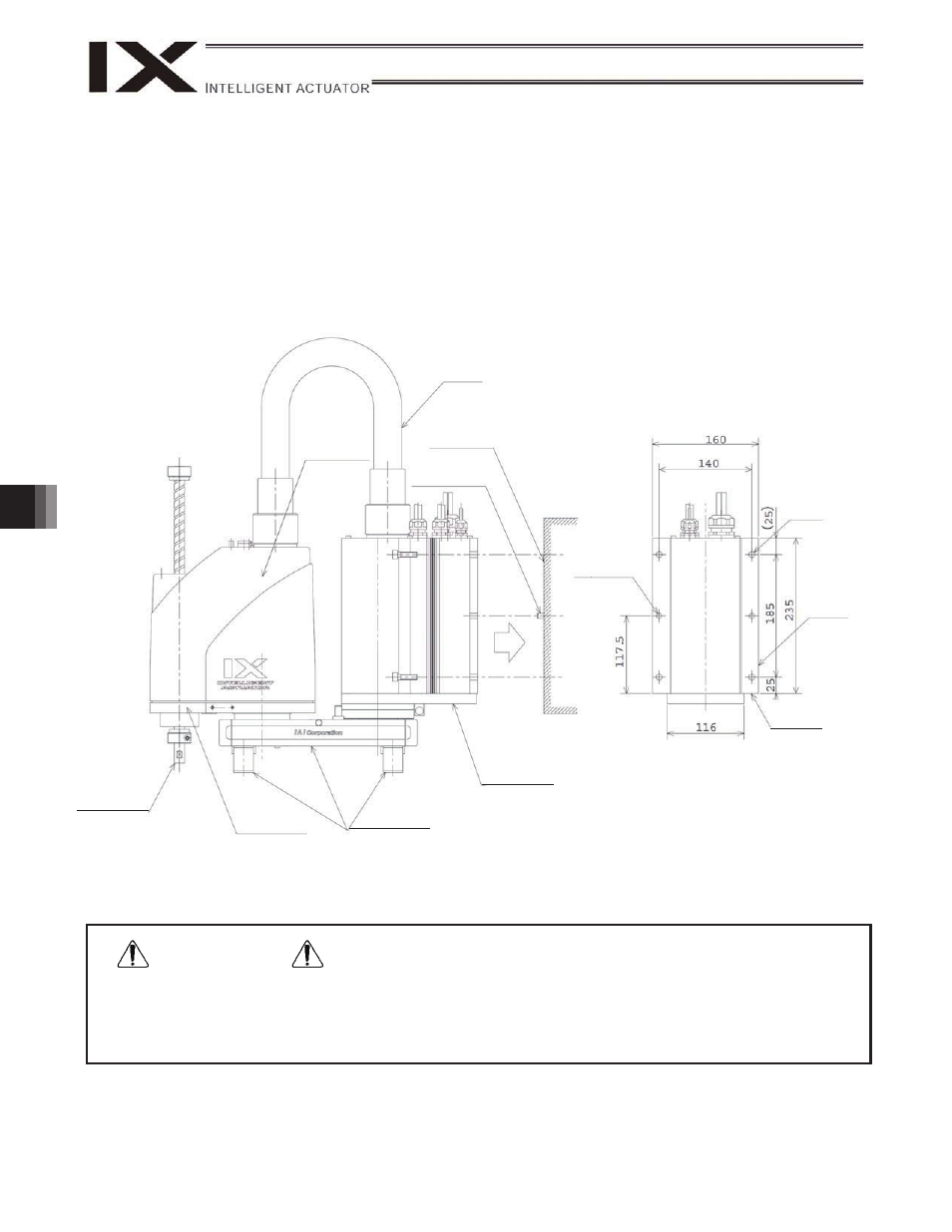
9. How to Install
x 2-8H10 reference holes are provided on the mounting surface of the base. Use these holes to prevent the
machine from dropping during installation or determine the machine position roughly. (Use the reference
surface of the base to determine the accurate position of the machine.)
x When installing the machine, affix the machine onto the mounting surface with arms 1 and 2 extended and
the machine supported by the base and arm 1.
* Be careful not to apply force on the rotational axis and arm 2 cover during the installation work.
x Use M8 hexagonal socket head bolts and washers to securely affix the robot.
(Tightening torque: 3.2 kgf-m)
For the hexagonal socket head bolts, use high-strength bolts of ISO10.9 or higher.
x Be careful not to apply force on the rotational axis, flexible cable or arm 2 cover during the installation work
(because it may cause these parts to bend, deform or otherwise trigger machine troubles).
x Tighten the hexagonal socket head bolts securely to the correct torque. If not, precision may drop and in the
worst case the robot may topple and cause an accident.
Caution
Warning
Flexible cable
Mounting wall
surface
Rotational axis
Arm 2
Support (base)
Support (arm 1)
2-
8H10
4-
9
Reference
surface
Reference
surface
Positioning pin
* The mounting direction is vertically reversed for the inverse specification.
Arm 2 cover