IAI America IX-UNN3515H User Manual
Page 26
20
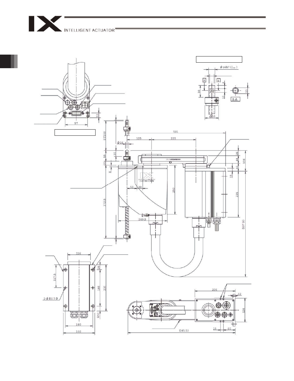
2. External Dimensions
IX-UNN3015H (Arm Length 350)
4-
9
16 counterbored, depth 0.5
(Counterbored on opposite
side)
T-slot for installing peripheral
equipment (M3, M4)
Reference
surface
4
(Me
ch
an
ica
l en
d
)
4 (
M
e
cha
ni
cal
e
nd)
Tapped hole for
installing peripheral
equipment (4-M4,
depth 12)
Same on opposite side
11 (inner diameter)
Quick joint
4, red
ALM (*2)
Quick joint
4, black
User spacer
Outer diameter
7, height
10, M4, depth 5 (*1)
Detail view of panel
User connector
Arm 1 stopper
Reference
surface
Arm 2 stopper
BK switch (brake
release switch)
Enlarged view of arm end
Reference surface
*1: The external force acting upon the spacer
shall be kept to 30 N or less in axial direction
or 2 N-m or less in rotating direction (per
spacer).
*2: The LED will actuate when the user wires
the applicable lines in such a way that 24
VDC is applied to the user-wired LED
terminal upon I/O output of a signal from the
controller.
Quick joint
4, white