Harrington Hoists and Cranes RHN - Rhino Wire Rope Hoist User Manual
Page 30
30
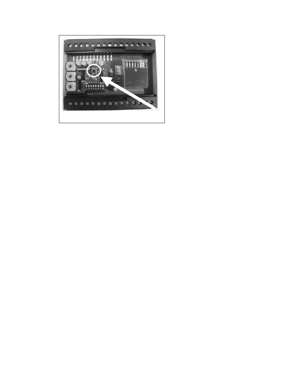
Figure 3-16
3.8 Hoist Limit Switches and Adjustment
The RHN wire rope hoist is equipped with a geared limit switch in the hoist control panel box. The limit switch is
equipped with four switches, all of which are utilized for standard hoist functions. The four limit switch positions are
as follows: S1 (Upper Safety Limit), S2 (Lower Limit), S3 (Upper Limit), and S4 (Speed Transition Limit).
The wire rope hoist is also equipped with a BLS (Block Limit Switch) as a standard feature.
3.8.1
Description and order of the limit switch function, including BLS as hook travels in the UP direction – See
Figure 3-17
.
S4
↑↑ (Speed Transition Geared Limit ): As the hook travels in the up direction, the first switch
position to activate will be S4
↑↑ . If the hoist is being operated in the up direction, high speed will be
deactivated when the S4
↑↑ switch is activated. The hoist will then remain in low speed until reaching the
switch position S3
↑ (Upper Limit).
S3
↑ (Upper Geared Limit): When the S3↑ switch position is activated, hook travel is disabled in the up
direction. The hoist can still be operated in down direction.
BLS
↑
(Block Operated Upper Limit Switch): See also
Figure 3-19
.
In addition to the geared limit switch, there is also a block operated upper limit switch (BLS
↑ ) installed
on the hoist. The BLS
↑
switch opens when the hook block lifts a weight and releases the tension from
the cable that holds the switch in the closed position. The BLS
↑
is adjusted so that the S3
↑ (Upper
Geared Limit) switch position activates first and the BLS
↑
second as a “back-up” safety.
S1
↑ (Upper Safety Geared Limit): In the event of a major malfunction where the upper limit switch
(S3
↑ ) and the block operated upper limit switch (BLS↑ ) are overrun, the S1↑ switch position is
activated and disables all directional movement and control. The only way to operate the hoist after the
S1
↑ switch has been activated is to eliminate the source of the problem and bridge (jumper) terminals
110 to 116 on the terminal strip located at the bottom of the hoist control panel box. WARNING: If the
S1 Geared Limit Switch position has been activated, a major malfunction has occurred.
Therefore, the equipment should be inspected by a qualified individual before attempting to
resume hoist operation.
3.8.2
Description and order of the limit switch function as the hook travels in the DOWN direction – See
Figure 3-18.
S4
↓ ↓ (Speed Transition Geared Limit): When the hook is located at the S3 (Upper Geared Limit)
position, and moving in the down direction, the hoist will remain at low speed until the hook is below the