Status led’s dc voltage test points – Teledyne GFC-7001T - Trace CO Analyzer User Manual
Page 259
Troubleshooting and ServiceTeledyne API – Model T300/T300M CO Analyzer
Teledyne
Analytical
Instruments
259
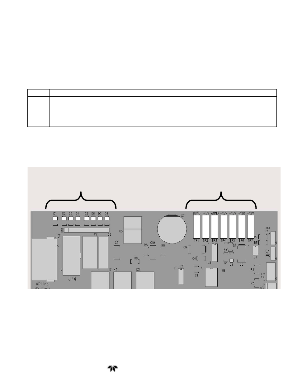
12.1.4.3. RELAY BOARD STATUS LEDS
There are eight LEDs located on the Relay Board. The most important of which is D1,
which indicates the health of the I
2
C bus. If D1 is blinking the other faults following
LEDs can be used in conjunction with DIAG menu signal I/O to identify hardware
failures of the relays and switches on the relay (see Section 12.1.3 and Appendix D).
Table 12-4: I
2
C Status LED Failure Indications
LED
FUNCTION
FAULT STATUS
INDICATED FAILURE(S)
D1
(Red)
I
2
C bus Health
(Watch Dog
Circuit)
Continuously ON
or
Continuously OFF
Failed/Halted CPU
Faulty Motherboard, Touchscreen or Relay Board
Faulty Connectors/Wiring between Motherboard,
Touchscreen or Relay Board
Failed/Faulty +5 VDC Power Supply (PS1)
STATUS LED’s
DC VOLTAGE TEST
POINTS
RELAY PCA
PN 04135
Figure 12-5:
Relay Board Status LEDs
- 1220 - Multipoint flammable gas and vapor detection system (50 pages)
- 212R - Thermal conductivity analyzer (28 pages)
- 235 - Thermal conductivity analyzer (38 pages)
- 275R - Portable turbine generator purge gas analyzer (21 pages)
- 2000A-EU - General purpose thermal conductivity analyzer (86 pages)
- 2000XTC - Thermal conductivity analyzer (40 pages)
- 2010A - Split architecture thermal conductivity analyzer (110 pages)
- 2010B - Split architecture thermal conductivity analyzer (98 pages)
- 2020 - Explosion proof thermal conductivity analyzer (80 pages)
- 2120 - Trace Nitrogen in Argon Analyzer (66 pages)
- 2120XL - Trace Nitrogen Analyzer (85 pages)
- 2230R - Process Hydrogen Analyzer (26 pages)
- 2240 – Portable Handheld Hydrogen Leak Detector, 3rd generation (updated 1/31/11) (30 pages)
- 2240 - Portable Handheld Hydrogen Leak Detector, 3rd generation (revision 2/29/08) (40 pages)
- 2240 – Portable Handheld Hydrogen Leak Detector, 2nd generation (13 pages)
- 2750 - Portable turbine generator gas analzyer (40 pages)
- 300P - Percent oxygen analyzer (24 pages)
- 306WA - Analog trace oxygen analyzer (46 pages)
- 311 - Portable trace oxygen analyzer (19 pages)
- 311D - Portable trace oxygen analyzer with digital meter (18 pages)
- 311XL - Portable trace oxygen analyzer (18 pages)
- 316RA / RB / RAD / RBD - Oxygen analyzers (24 pages)
- 319R - Oxygen analyzer (23 pages)
- 320 Series - Portable oxygen detectors (24 pages)
- 326, 327 and 328 - Oxygen analyzers (45 pages)
- 329R - Oxygen analyzer (22 pages)
- 335 - Analog control room monitor for personnel safety (24 pages)
- 356WA - Analog trace oxygen analyzer (42 pages)
- 3000MA - Paramagnetic oxygen analyzer (63 pages)
- 3000MA - Paramagnetic oxygen analyzer Addendum (2 pages)
- 3000MB - Paramagnetic oxygen analyzer (59 pages)
- 3000PA - General purpose percent oxygen analyzer (69 pages)
- 3000PAEU - General purpose percent oxygen analyzer (78 pages)
- 3000PB - Bulkhead mount percent oxygen analyzer (82 pages)
- 3000TA - General purpose trace oxygen analyzer (75 pages)
- 3000TA-EU - General purpose trace oxygen analyzer (89 pages)
- 3000TA-XLEU - Trace oxygen analyzer (108 pages)
- 3000TB - Bulkhead mount trace oxygen analyzer (78 pages)
- 3000TB-XL - Trace oxygen analyzer (78 pages)
- 3000ZA - Trace oxygen analyzer (81 pages)
- 3000ZA-3X - Trace oxygen analyzer (72 pages)
- 3000ZA2G - Zirconium oxide analyzer (72 pages)
- 3000 Ultra Trace - PPB oxygen analyzer (72 pages)
- 3010MA - Paramagnetic oxygen analyzer, includes 0-100% range (88 pages)
- 3010MA – Paramagnetic oxygen analyzer, no 0-100% range – (superceded) (88 pages)