Description of icons and leds – Burkert Type 8076 User Manual
Page 42
40
Adjustmentandcommissioning
9.8.
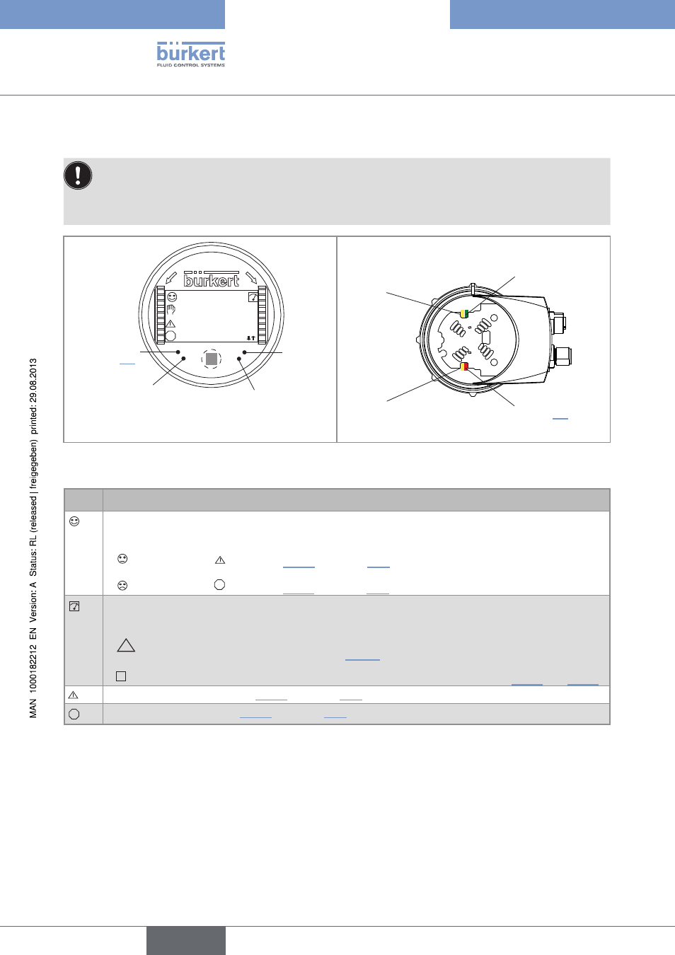
Description of icons and leDs
• The LEDs of the display module are duplicated on the electronic board that is located under the display
module: these LEDs become visible when the device is not equipped with the display module.
• The yellow LED related to a transistor output is deactivated if the transistor output is configured in pulse
mode ("Pulse").
OP
EN
LO
CK
flow_l
600.0l/h
flow_m3
0.60/h
ERR
Red LED:
shows an error;
see chap. 10.3
not used
Yellow LED: shows that transis-
tor 1 is switched
Yellow LED: shows that transistor 2
is switched
Red LED: shows an error;
see chap. 10.3
Yellow LED: shows that
transistor 2 is switched
Green LED: shows that
the device is energized
Yellow LED: shows that
transistor 1 is switched
Figure 38 :
Position of the icons and description of the LEDs
icon
possible cause and alternatives
Sensor input frequency within the defined ranges
The alternatives, in this position, if monitoring of the sensor input frequency is activated, are:
•
, associated with
: see chap. 9.14.2 and chap. 10.3
•
, associated with
ERR
: see chap. 9.14.2 and chap. 10.3
The device is measuring.
The alternative icons in this position are:
•
HOLD
!
flashing: HOLD mode activated (see chap. 9.13.1)
•
T
: running check that the outputs are working and behaving correctly (see chap. 9.15.2 and 9.15.3)
"warning" message; See chap. 9.14.2 and chap. 10.3
ERR
"error" message; See chap. 9.14.2 and chap. 10.3
English
Type 8026- 8036- 8076