Burkert Type 8695 User Manual
Page 24
24
Installation
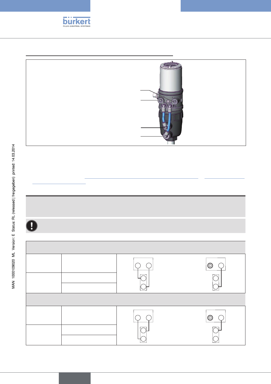
3. install pneumatic connection between control head and actuator
Pilot air outlet 2
1
Pilot air outlet 2
2
Upper pilot air port
Lower pilot air port
Figure 13:
Installing the pneumatic connection between control head and actuator, series 20xx
→
Screw the plug-in hose connectors onto the control head and the actuator.
→
Using the hoses supplied in the accessory kit, make the pneumatic connection between the control head and
actuator with the following “Table 1: Pneumatic connection to actuator CFA and CFB” or “Table 2: Pneumatic
connection to actuator CFI”.
noTe!
Damage or malfunction due to ingress of dirt and moisture.
▶ To comply with degree of protection IP65 / IP67, connect the pilot air outlet
(only for CFA or CFB) which is
not required to the free pilot air port of the actuator or seal with a plug.
“In rest position” means that the pilot valves of the control head Type 8695 are isolated or not actuated.
Control function a (CFa)
Process valve closed in rest position (by spring force)
Control head
Pilot air outlet
2
2
2
1
or
2
2
2
1
Actuator
Upper pilot air port
Lower pilot air port
Control function B (CFB)
Process valve open in rest position (by spring force)
Control head
Pilot air outlet
2
2
2
1
or
2
2
2
1
Actuator
Upper pilot air port
Lower pilot air port
Table 1:
Pneumatic connection to actuator CFA and CFB
english
Type 8695