Equipment staging - pc & cr10x communication, 1 introduction – YSI Vertical Profiler Systems User Manual
Page 46
YSI Profiler System USER Manual
Section 4
Equipment Staging – PC / CR10X Communication
4.1 Introduction
You will now open LoggerNet™ and set up a connection between your PC and the CR10X data
logger. You will also set up your modem. Finally, you will proceed to download the program
(*.dld) that you created with YSI Profile Wizard. Communication with the CR10X will allow
you to perform important pre-deployment tests before locating the Profiler at a monitoring site.
To connect your PC to the CR10X (housed within the Profiler Controller Assembly) you will
need a Diagnostic Cable (provided with your system). One end is a 9-pin standard RS-232
connector; the other connector fits the Diagnostics port (J3) of the Controller. In addition, you
will learn to use LoggerNet™ to set up modem communication using the Setup function. The
most commonly used means of wireless communications in this system are either a cellular
modem or an IP address. Refer to your LoggerNet manual for detailed instructions. Below you
will see a sample setup.
You should proceed through the above mentioned steps in a stable environment if possible. If you
configure and test your profiling system in this manner, you are less likely to make an error that
would cost you valuable time once in the field.
4.2 Setting Up Communication from PC to Station (CR10X)
Use this section in conjunction with the LoggerNet™ manual. After installation, LoggerNet™
will appear in the Programs folder of the Start Menu or as an icon on Windows Desktop.
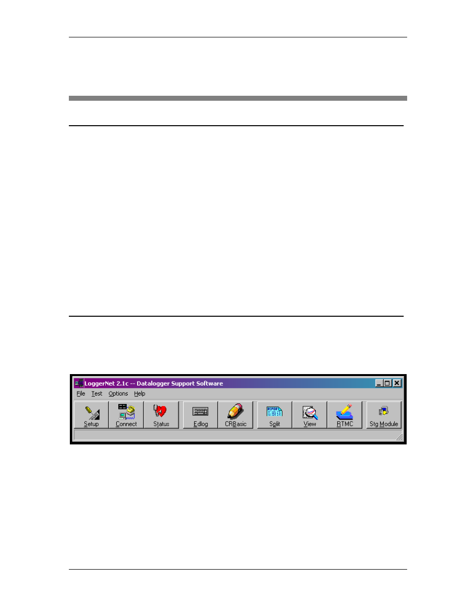
Double click the LoggerNet™ icon to open the following window.
Click Setup (far left button above) to open the Setup screen shown below. At any time you may
click the Undo button to reverse changes you have made.
Now proceed with the setup.
YSI Environmental
669523 Rev B
Page 4-1