10 epo command connection (emergency power off), Epo command connection (emergency power off), Ep o ep o – GE Industrial Solutions TLE Series 225-500 Installation Guide User Manual
Page 47: Critical power, 24 vdc for external (uvr) battery breaker
Critical Power
Modifications reserved
Page 47/54
GE_UPS_ISG_TLE_SUL_M22_M50_1US_V010.docx
Installation Guide TLE Series 225 - 500 UL S1
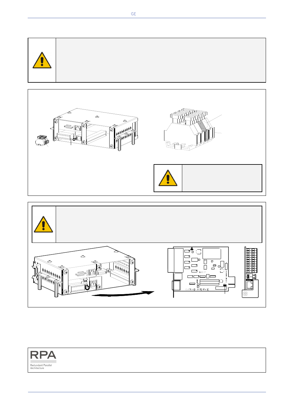
4.10 EPO COMMAND CONNECTION (EMERGENCY POWER OFF)
WARNING !
The connection of an emergency button EPO (Emergency Power Off) must be
performed by QUALIFIED SERVICE PERSONNEL only when the UPS is
COMPLETELY POWERED DOWN.
BE AWARE !
The reliability of the system depends on this contact NC (Normally Closed)!
An Emergency button (Normally Closed voltage-free contact) can be connected on terminals XA /
EPO-1, EPO-2. Max. rating XA terminals: 2.5mm
2
.
Fig. 4.10-1 XA terminal block for EPO command connection
When opened, this contact causes the immediate
opening of the Contactors K6 and K7 as well as
the shut-down of Rectifier, Inverter and Static-
Switch.
NOTE !
This procedure could imply a
Load shut-down.
NOTE !
To operationalize this function, in case that the UPS was provided with one or
more cards “P4 - Customer Interface”, there must be on each card the following:
- Remove the cable short-circuiting terminals X2 / 1, 2 (see Fig. 4.10-2).
- Remove the Jumper JP2 (see Fig. 4.10-2).
Fig. 4.10-2 X2 terminal block and Jumper JP2 on the P4 – Customer Interface Board
When the EPO has been activated, the system must be restored as follows:
Realize the push-button EPO (contact on XA / EPO-1, EPO-2 is closed again).
Press the key “Inverter OFF” on the Control Panel (see User Manual to Section 6.5).
In case of a Parallel System press the key “O” (Inverter OFF) on the Control Panel of
each unit connected on the Parallel Bus and having its output switch Q1 closed.
SGSE_400-500_S3_Custom
er interface-XA_01
Customer Interface
1
12 13 14 15 16
17 18 19 20
21 22
2 3 4 5 6
7 8 9
10 11
XA
EPO
EPO
+
-
TLES_UL_400-500
_S1_Terminals XA_
01
XA
EP
O
EP
O
+
-
24 Vdc for
External (UVR)
Battery Breaker
X2
10
9
8
21
19 20
22
11
SGSE_
600_S1
_Custom
er interf
ace-X2
EPO_0
1
SNMP card
14
13
12
2
1
7
6
5
16
15
4
3
18
17
X1
X2
J1
JP2
1
2
8
19
21
22
20
10
11
9
17
18
16
15
7
6
5
4
12
14
13
3
2
1
X1
X2
J1
SE_
40
0-
50
0_
S1_C
usto
m
er
interfac
e-JP
2_01