Ab c – GE Industrial Solutions TLE Series 225-500 Installation Guide User Manual
Page 32
Critical Power
Modifications reserved
Page 32/54
GE_UPS_ISG_TLE_SUL_M22_M50_1US_V010.docx
Installation Guide TLE Series 225 - 500 UL S1
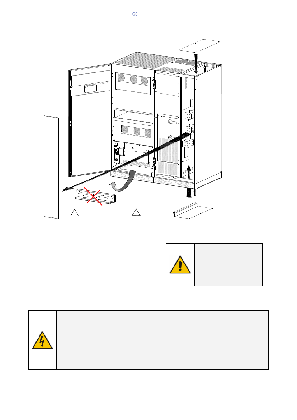
TLE Series 400 & 500 Access to the bus bars for the cable connections
Fig. 4.8-2 TLE Series 400 & 500 - Access to connection bus bars
To access Input, Output and Battery connections
proceed as follows:
Remove the front protection panel “A”.
Bottom entry cables: remove the plate “B”.
Top entry cables: remove the plate “C”.
NOTE !
For
UPS
correct
operation, the input
utility phase rotation
must be clock-wise.
CAUTION !
Panel “A, B and C” should never be removed or replaced with power applied to the
UPS.
These panels are in close proximity to 480V live buss bars.
Always disconnect the rectifier, bypass, load and battery sources from the UPS
before removing or replacing these panels.
If not serious injury or death could occur!
Q1
I ON
0
O
FF
A
B
C
Utility mains / Battery / Output load
Bottom entry cables
TLES_UL_400-
500_S1_U
PS connec
tion_01US
1
2
Q2
I ON
0
O
FF
E
PO
E
PO
- +
Utility mains / Battery / Output load
Top entry cables
!
Please remove
the plate (B) before
drilling any wholes
!
It's MANDATORY REMOVE
the base reinforcement (C)
See Chapter 4.4.1
D