GE Industrial Solutions TLE Series 225-500 Installation Guide User Manual
Page 35
Critical Power
Modifications reserved
Page 35/54
GE_UPS_ISG_TLE_SUL_M22_M50_1US_V010.docx
Installation Guide TLE Series 225 - 500 UL S1
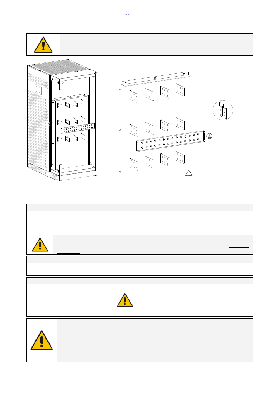
4.8.2 TLE Series 225 & 250 - Power connection with Dual Input Utility
NOTE !
Neutral of Rectifier input and Neutral of Bypass input must be coming from the
same input bar.
Fig. 4.8.2-1 TLE Series 225 & 250 - Power connections with Dual Input Utility
Power connection cables are connected to bus bars using M10 bolts.
The bolts of the connection cables must be tightened with a torque wrench at 355 Lb-in / 40 Nm.
Dual Input Utility - Rectifier / Bypass
L1-1
Rectifier phase A (L1)
L1-2
Bypass phase A (L1)
L2-1
Rectifier phase B (L2)
L2-2
Bypass phase B (L2)
L3-1
Rectifier phase C (L3)
L3-2
Bypass phase C (L3)
PE
Ground
N
Neutral
NOTE !
The interconnection links BR1, BR2 and BR3 (option) on the input bus bars MUST BE
REMOVED (see Fig. 4.8.4-2).
Output Load
L1
Load phase A (L1)
L2
Load phase B (L2)
L3
Load phase L3
N
Neutral
Ground
External Battery connection
+
Positive pole of the battery
UPS PARALLELED ON THE SAME BATTERY:
This configuration is not possible for UPS Parallel
System TLE Series 225 & 250.
Before closing the “External Battery Fuses”, verify for
correct polarity of the battery connection.
-
Negative pole of the battery
PE
Battery cabinet ground
NOTE !
To meet standards concerning electromagnetic compliance, the connection between the UPS
and external Battery must be done by using a shielded cable or suitable shielded (steel) conduit!
This UPS is only designed to operate in a wye-configured electrical system with a solidly
grounded neutral.
If the UPS is equipped with an input bypass transformer, the secondary of the transformer
must be wye-configured with neutral solidly grounded.
+
-
Typical installation
using common NEMA
two hole lugs
PE
TLES_UL_22
5-250_S1_
UPS conne
ction_01U
S
1
Rectifier
Utility
L1-1
N
Utility Neutral
Load Neutral
2
Bypass
Utility
L1-2
Load
L1
L2-1
L2-2
L2
L3-1
L3-2
L3
INTERCONNECTIONS LINKS
BR1, BR2 and BR3
MUST BE REMOVED
(see Fig. 4.8.2-2)
!