GE Industrial Solutions TLE Series 225-500 Installation Guide User Manual
Page 37
Critical Power
Modifications reserved
Page 37/54
GE_UPS_ISG_TLE_SUL_M22_M50_1US_V010.docx
Installation Guide TLE Series 225 - 500 UL S1
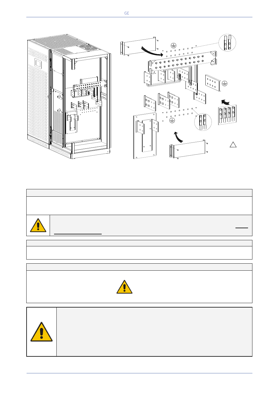
4.8.3 TLE Series 400 & 500 - Power connection with Common Input Utility
Fig. 4.8.3-1 TLE Series 225 & 250 - Power connections Common Input Utility
Power connection cables are connected to bus bars using M10 bolts.
The bolts of the connection cables must be tightened with a torque wrench at 355 Lb-in / 40 Nm.
Common Input Utility - Rectifier / Bypass
L1-1
Rectifier + Bypass Phase A (L1)
L2-1
Rectifier + Bypass Phase B (L2)
N
Neutral
L3-1
Rectifier + Bypass Phase C (L3)
PE
Ground
NOTE !
The interconnection links BR1, BR2 and BR3 (option) on the input bus bars MUST
REMAIN CONNECTED (see Fig. 4.8.3-2).
Output Load
L1
Load phase A (L1)
L2
Load phase B (L2)
L3
Load phase L3
N
Neutral
Ground
External Battery connection
+
Positive pole of the battery
UPS PARALLELED ON THE SAME BATTERY:
This configuration is not possible for UPS Parallel
System TLE Series 225 & 250.
Before closing the “External Battery Fuses”, verify for
correct polarity of the battery connection.
-
Negative pole of the battery
PE
Battery cabinet ground
NOTE !
To meet standards concerning electromagnetic compliance, the connection between the
UPS and external Battery must be done by using a shielded cable or suitable shielded (steel)
conduit!
This UPS is only designed to operate in a wye-configured electrical system with a solidly
grounded neutral.
If the UPS is equipped with an input bypass transformer, the secondary of the transformer
must be wye-configured with neutral solidly grounded.
INTERCONNECTIONS LINKS
BR1, BR2 and BR3
MUST REMAIN CONNECTED
Q2
Q1
TLES_UL_4
00-500_S1
_UPS conn
ection comm
on_Top_01
US
+
-
PE
PE
N
Utility Neutral
Load Neutral
Typical installation
using common NEMA
two hole lugs
Load
Typical installation using
common NEMA two hole lugs
PE
PE
(Use for top entry cables)
L3
L2
L1
L3-1
L2-1 L1-1
1
Rectifier &
Bypass
Utility
B
R2
BR3
BR1
(Use for bottom entry cables)
PE
Attention:
Use only as additional PE
!
Position of the cover protection
with top cable entry
Position of the
cover protection with
bottom cable entry