3 control bus cable location, Control bus cable location, Access to the control bus connection – GE Industrial Solutions TLE Series 225-500 Installation Guide User Manual
Page 45: Control bus cables connection, Critical power, View electronic module on intermediate unit, 12 ep o ep o
Critical Power
Modifications reserved
Page 45/54
GE_UPS_ISG_TLE_SUL_M22_M50_1US_V010.docx
Installation Guide TLE Series 225 - 500 UL S1
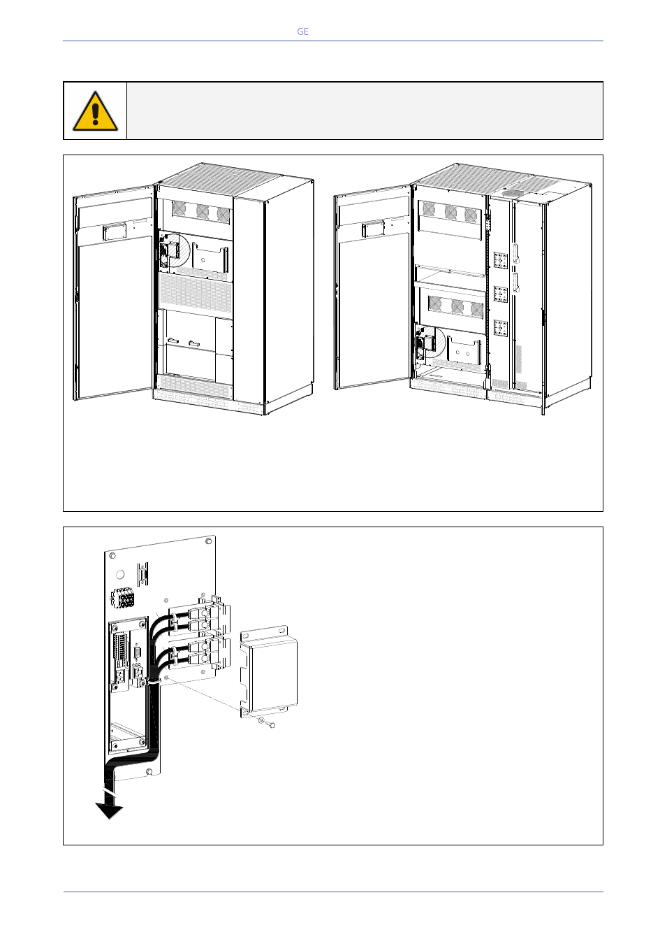
4.9.3 Control bus cable location
WARNING !
This installation must be verified by trained personnel before the initial start-up.
ENSURE THAT THE UPS INSTALLATION IS COMPLETELY POWERED DOWN.
Fig. 4.9.3-1 TLE Series 400 & 500
View electronic module on intermediate unit
Fig. 4.9.3-2 TLE Series 400 & 500
View electronic module on intermediate unit
Access to the control bus connection
The communication bus cable connectors are placed on the two boards “P13/P14 – IM0022 – Bus
Interface Board” (see Fig. 4.9.3-1 and 4.9.3-2).
Fig. 4.9.3-3 View electronic module on intermediate unit
Control bus cables connection
Plug the cables J1A – J2A (1/2/3/4/5) and J1B –
J2B (1/2/3/4/5) on the connectors J1A – J2A and
J1B – J2B placed on the two boards “P13/P14 –
IM0022 – Bus Interface Board”.
Fix the communication bus cables J1A – J2A
(1/2/3/4/5) and J1B – J2B (1/2/3/4/5) with the
provided cable clamps “A”.
TLES_UL_22
5-250_S1_
RPA conne
ction_01
Q1
I ON
0
OF
F
Q2
I ON
0
OF
F
1
2
EP
O
EP
O
-
+
TLES_320-
400_S1_RP
A connect
ionE_01
1
2
EP
O
EP
O
-
+
0 Off
I O
N
0 Off
I O
N
Q1
Q2
J2
J1
J2
J1
A
B
J1B/1
J1A/2÷5
J1A/1
J1B/2÷5
-
+
EP
O
EP
O
TLES_160-
400_S1_R
PA connec
tion_02