8 wiring connection, Wiring connection – GE Industrial Solutions TLE Series 225-500 Installation Guide User Manual
Page 31
Critical Power
Modifications reserved
Page 31/54
GE_UPS_ISG_TLE_SUL_M22_M50_1US_V010.docx
Installation Guide TLE Series 225 - 500 UL S1
4.8 WIRING CONNECTION
WARNING !
UPS installation and connection must be performed by QUALIFIED SERVICE
PERSONNEL only.
Refer to the “Safety prescriptions - Installation” described on Chapter 1.
In case of UPS equipped with options or customized parts not covered by this
manual, please consult the appropriate technical documentation before proceeding
with electrical connections.
Carefully read the following recommendations before proceeding:
Ensure that the AC and DC external isolators are Off, and prevent their inadverted operation.
Do not close any external isolators prior to the commissioning of the equipment.
The input/output cables must be connected in clockwise phase rotation for both Bypass and
Rectifier Input Bars if separate, taking care to avoid risk of short circuit between different poles.
The grounding and neutral connection of the electrical system must be in accordance with local
regulations.
In case of additional cabinets containing batteries, input/ output transformers, etc, their ground
terminals must be connected to the UPS main ground terminal.
Once the power cables have been connected, re-install the internal safety shields and close the
cabinets by re-installing all external panels.
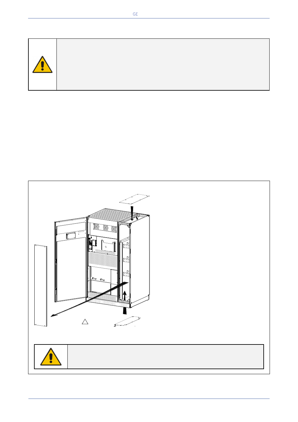
TLE Series 225 & 250 Access to the bus bars for the cable connections
Fig. 4.8-1 TLE Series 225 & 250 - Access to connection bus bars
To access Input, Output and
Battery connections proceed as
follows:
Remove the front protection
panel “A”.
Bottom entry cables: remove
the plate “B”.
Top entry cables: remove the
plate “C”.
NOTE !
For UPS correct operation, the input utility phase rotation must be clock-
wise.
A
B
Utility mains / Battery / Output load
Bottom entry cables
TLES_UL_225-
250_S1_U
PS connec
tion_01US
Utility mains / Battery / Output load
Top entry cables
!
Please remove
the plate (B) before
drilling any wholes
Q1
I ON
0
O
FF
Q2
I ON
0
O
FF
1
2
E
PO
E
PO
-
+
C